Contents
- Delivery contents
- Installation
- Audi A2
- Audi A3/S3 8L (model year 1998 - 1999)
- Audi A4/S4 B5 (model year 1998 - 1999)
- Audi A6/S6 C5 (up to model year 2000)
- Audi A3/S3 8L (from model year 2000)
- Audi A4/S4/RS4 B5 (from model year 2000)
- Audi A6/S6/RS6/Allroad C5 (from model year 2001)
- Audi TT 8N (from model year 2000)
- Audi A4/S4 B6
- Audi A4/S4/RS4 B7
- Seat Exeo 3R
- VW Golf Mk4 (up to model year 2001)
- VW Passat 3B (up to model year 2000)
- VW Bus T4
- Skoda Octavia 1U (up to model year 1999)
- VW Golf Mk4 (from model year 2002)
- VW Passat 3BG (from model year 2001)
- VW Sharan I / Ford Galaxy WGR / Seat Alhambra I
- Skoda Superb 3U
- Skoda Octavia 1U (from model year 2000)
- Audi A3/S3/RS3 8P
- Audi TT/TTS/TTRS 8J
- Audi R8 42
- Golf Mk5 platform (e.g. Golf Mk5, Passat 3C, Touran, Octavia II, Leon 1P)
- FIS-Control 2.x
- Supported cars
- The steps of evolution
- Connectors of the FIS-Control
- Installation (for example in the Audi A4 B7)
- CAN bus or 3-wire-bus?
- Coding of the instrument cluster
- 3-wire-bus mode
- CAN bus mode
- How to change the coding of the cluster?
- Coding with WBH-Diag
- Coding with VCDS
- Coding of the FIS-Control
- Configuration of the FIS-Control
- Using the FIS-Control
- The main menu
- Presets
- Measurement
- Read DTC
- Settings
- Control unit
- Scale
- Presets
- Save settings
- Sensors
- Mask
- Startlogo
- Autostart
- Boost
- Headline
- Flash memory
- Units
- Tweaks
- Logging
- GPS Mouse
- User mods
- Language
- Collections
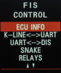
- ECU Info
- K-LINE<->UART
- UART<->DIS
- Snake
- Relays
- About
- Firmware updates
- Troubleshooting
Delivery contents
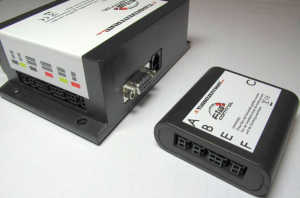
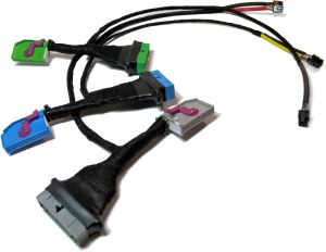
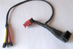
The FIS-Control consists of the main control unit and the car specific cable set.The control unit is the same for all supported car models. With the correct cable set it can be used with all cars.
Installation
Dependent on the car, the cable set is either inserted into the cable harness of the instrument cluster or plugged into the CAN gateway. There is no need to cut any wires to do so. Installation (and also removal) of the FIS-Control will not cause any modification or damage to the original cable harness.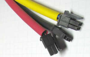
Audi A2
Installation
- Turn off the ignition and pull the key out.
- Remove the cluster instrument.
- Plug the included cable set between the cluster and the original cable harness.
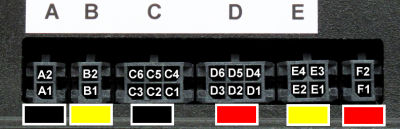
- Plug the connectors of the cable set into the FIS-Control.
- Socket A: 2-pin plug with black shrinking hose of the blue cable set
- Socket B: 2-pin plug with yellow shrinking hose of the green cable set
- Socket C: 6-pin plug with black shrinking hose of the gray cable set
- Socket D: 6-pin plug with red shrinking hose of the gray cable set
- Socket E: 4-pin plug with yellow shrinking hose of the gray cable set
- Socket F: not used
- Insert cluster and place the FIS-Control box at a suitable location.
Coding of the instrument cluster
To be able to send data to the display of the instrument cluster, the FIS-Control uses the CAN bus addresses of the telematics and phone module. The instrument cluster only accepts these addresses when these both devices are enabled in the CAN bus installation list. This is done by coding the adaptation channel 62 of the instrument cluster to the values "15". More information about that in the related chapter.Alternatively the FIS-Control also use the addresses of the navigation system and the radio. This is only possible when none of these devices is already installed. The adaptation channel 62 has to be coded to the value "5" in this case.
Please note: As long as the instrument cluster is not properly coded, the FIS-Control will not work and the normal board computer will not respond to button presses of the wiper control stalk.
Compatibility
No known limitations.Audi A3/S3 8L (model year 1998 - 1999)
Audi A4/S4 B5 (model year 1998 - 1999)
Audi A6/S6 C5 (up to model year 2000)
Installation
- Turn off the ignition and pull the key out.
- Remove the cluster instrument.
- Plug the included cable set between the cluster and the original cable harness.
- Plug the connectors of the cable set into the FIS-Control.
- Socket A: 2-pin plug with black shrinking hose of the blue cable set
- Socket B: 2-pin plug with yellow shrinking hose of the blue cable set
- Socket C: 6-pin plug with black shrinking hose of the red cable set
- Socket D: 6-pin plug with red shrinking hose of the red cable set
- Socket E: not used
- Socket F: not used
- Insert cluster and place the FIS-Control box at a suitable location.
Coding of the instrument cluster
To be able to send data to the display of the instrument cluster, the FIS-Control uses the 3-wire-bus. The 3-wire-bus has to enabled in the instrument cluster if necessary. If the current coding value is less than "16000", then "16000" has to be added. More information about that in the related chapter.Please note: As long as the instrument cluster is not properly coded, the FIS-Control will not work and the normal board computer will not respond to button presses of the wiper control stalk.
Compatibility
Unlike the FIS-Control, the FIS-Control Light does not support the 3-wire-bus and is not compatible.If a radio is installed, that normally displays the station name in the cluster display, this will be dropped as soon as the FIS-Control is installed. The output from navigation systems (guiding directions and station names) will still be shown.
Audi A3/S3 8L (from model year 2000)
Installation
- Turn off the ignition and pull the key out.
- Remove the cluster instrument.
- Plug the included cable set between the cluster and the original cable harness.
- Plug the connectors of the cable set into the FIS-Control.
- Socket A: 2-pin plug with black shrinking hose of the blue cable set
- Socket B: 2-pin plug with yellow shrinking hose of the green cable set
- Socket C: 6-pin plug with black shrinking hose of the gray cable set
- Socket D: 6-pin plug with red shrinking hose of the gray cable set
- Socket E: 4-pin plug with yellow shrinking hose of the gray cable set
- Socket F: not used
- Insert cluster and place the FIS-Control box at a suitable location.
Coding of the instrument cluster
To be able to send data to the display of the instrument cluster, the FIS-Control uses the CAN bus addresses of the telematics and phone module. The instrument cluster only accepts these addresses when these both devices are enabled in the CAN bus installation list. This is done by coding the adaptation channel 62 of the instrument cluster to the values "15". More information about that in the related chapter.Alternatively the FIS-Control also use the addresses of the navigation system and the radio. This is only possible when none of these devices is already installed. The adaptation channel 62 has to be coded to the value "5" in this case.
If a navigation system is installed that is connected to the instrument cluster via 3-wire-bus, the FIS-Control should be also run in 3-wire-bus-mode. There is no need to change the cluster coding in that case.
Please note: As long as the instrument cluster is not properly coded, the FIS-Control will not work and the normal board computer will not respond to button presses of the wiper control stalk.
Compatibility
The instrument clusters with the part number "8L0 920 933 N" (software version "M73 D07") and part number "8L0 920 930 B" (software version "VDO D09") do not support the telematics channel on the CAN bus. Therefore the FIS-Control has to use the address of the navigation system or the 3-wire-bus (only available with the FIS-Control, not with the FIS-Control Light). So the FIS-Control can only be used with this cluster, if no navigation system (that displays data on the screen of the instrument cluster) is installed, or the navigation system uses the 3-wire-bus.With the instrument cluster with the part number "8L0 920 930 A" and the software version "M73 D16" the FIS-Control can only be used in 3-wire-bus mode. Additionally it is not possible to display pixel graphics. That means: no startlogo, no line graphs, no boost bar graph, no snake game. The FIS-Control Light can not be used with this cluster.
Audi A4/S4/RS4 B5 (from model year 2000)
Installation
- Turn off the ignition and pull the key out.
- Remove the cluster instrument.
- Plug the included cable set between the cluster and the original cable harness.
- Plug the connectors of the cable set into the FIS-Control.
- Socket A: 2-pin plug with black shrinking hose of the blue cable set
- Socket B: 2-pin plug with yellow shrinking hose of the green cable set
- Socket C: 6-pin plug with black shrinking hose of the gray cable set
- Socket D: 6-pin plug with red shrinking hose of the gray cable set
- Socket E: 4-pin plug with yellow shrinking hose of the gray cable set
- Socket F: not used
- Insert cluster and place the FIS-Control box at a suitable location.
Coding of the instrument cluster
To be able to send data to the display of the instrument cluster, the FIS-Control uses the CAN bus addresses of the telematics and phone module. The instrument cluster only accepts these addresses when these both devices are enabled in the CAN bus installation list. This is done by coding the adaptation channel 62 of the instrument cluster to the values "15". More information about that in the related chapter.Alternatively the FIS-Control also use the addresses of the navigation system and the radio. This is only possible when none of these devices is already installed. The adaptation channel 62 has to be coded to the value "5" in this case.
If a navigation system is installed that is connected to the instrument cluster via 3-wire-bus, the FIS-Control should be also run in 3-wire-bus-mode. There is no need to change the cluster coding in that case.
Please note: As long as the instrument cluster is not properly coded, the FIS-Control will not work and the normal board computer will not respond to button presses of the wiper control stalk.
Compatibility
The instrument clusters with the part number "8D0 920 930 C" (software version "VDO D09") and part number "8D0 920 930 Q" (software version "VDO D07") do not support the telematics channel on the CAN bus. Therefore the FIS-Control has to use the address of the navigation system or the 3-wire-bus (only available with the FIS-Control, not with the FIS-Control Light). So the FIS-Control can only be used with this cluster, if no navigation system (that displays data on the screen of the instrument cluster) is installed, or the navigation system uses the 3-wire-bus.With the instrument cluster with the part number "8D0 920 930 A" (software version "M73 D16") it is not possible to display pixel graphics. That means: no startlogo, no line graphs, no boost bar graph, no snake game. This cluster only supports the 3-wire-bus.
Audi A6/S6/RS6/Allroad C5 (from model year 2001)
Installation
- Turn off the ignition and pull the key out.
- Remove the cluster instrument.
- Plug the included cable set between the cluster and the original cable harness.
- Plug the connectors of the cable set into the FIS-Control.
- Socket A: 2-pin plug with black shrinking hose of the blue cable set
- Socket B: 2-pin plug with yellow shrinking hose of the green cable set
- Socket C: 6-pin plug with black shrinking hose of the gray cable set
- Socket D: 6-pin plug with red shrinking hose of the gray cable set
- Socket E: 4-pin plug with yellow shrinking hose of the gray cable set
- Socket F: not used
- Insert cluster and place the FIS-Control box at a suitable location.
- Optional: To also reach the control units on the L-line, a wire between the screw terminal "L-Line" and pin 15 of the OBD socket has to be installed. Additionally the user mod "L-Line A6" has to be enabled in the settings menu.
Coding of the instrument cluster
To be able to send data to the display of the instrument cluster, the FIS-Control uses the CAN bus addresses of the telematics and phone module. The instrument cluster only accepts these addresses when these both devices are enabled in the CAN bus installation list. This is done by coding the adaptation channel 62 of the instrument cluster to the values "15". More information about that in the related chapter.Alternatively the FIS-Control also use the addresses of the navigation system and the radio. This is only possible when none of these devices is already installed. The adaptation channel 62 has to be coded to the value "5" in this case.
Please note: As long as the instrument cluster is not properly coded, the FIS-Control will not work and the normal board computer will not respond to button presses of the wiper control stalk.
Compatibility
The FIS-Control Light does not have a connector for the L line. Therefore the following control units can not be reached via OBD: auto HVAC, auxiliary heat, central locks, navigation system, interior monitor, xenon range regulation, radio, tire pressure, park assist.If a telephone module is installed, the upper two lines of the instrument cluster display can not be used by the FIS-Control.
Audi TT 8N (from model year 2000)
Installation
- Turn off the ignition and pull the key out.
- Remove the cluster instrument.
- Plug the included cable set between the cluster and the original cable harness.
- Plug the connectors of the cable set into the FIS-Control.
- Socket A: 2-pin plug with black shrinking hose of the blue cable set
- Socket B: 2-pin plug with yellow shrinking hose of the green cable set
- Socket C: 6-pin plug with black shrinking hose of the gray cable set
- Socket D: not used
- Socket E: 4-pin plug with yellow shrinking hose of the gray cable set
- Socket F: not used
- Insert cluster and place the FIS-Control box at a suitable location.
Please note: The 6-pin plug with red shrinking hose of the gray cable is not used and should not be plugged in.
Coding of the instrument cluster
To be able to send data to the display of the instrument cluster, the FIS-Control uses the CAN bus addresses of the telematics and phone module. The instrument cluster only accepts these addresses when these both devices are enabled in the CAN bus installation list. This is done by coding the adaptation channel 62 of the instrument cluster to the values "15". More information about that in the related chapter.Alternatively the FIS-Control also use the addresses of the navigation system and the radio. This is only possible when none of these devices is already installed. The adaptation channel 62 has to be coded to the value "5" in this case.
Please note: As long as the instrument cluster is not properly coded, the FIS-Control will not work and the normal board computer will not respond to button presses of the wiper control stalk.
Please note: If a radio is installed that shows the station names on the upper segment of the instrument cluster display, an alternate firmware may be installed on the FIS-Control, so that it can also show data on the upper two lines of the display.
Compatibility
In the TT the FIS-Control only works together with instrument cluster with CAN bus. That are all cluster that have "920" as part of their part number, only exception is the cluster with the part number "8N1 920 880 A".The instrument clusters with the following part numbers don't support the telematics channel on the CAN bus: "8N1 920 880 G", "8N1 920 880 H", "8N1 920 930 Q", "8N1 920 930 T". The FIS-Control has to use the address of the navigation system instead. Is there already a navigation system installed via CAN bus, the FIS-Control will not be useable with these clusters.
With the instrument cluster with the part numbers "8N1 920 880 G" and "8N1 920 880 C"it is not possible to display pixel graphics. That means: no startlogo, no line graphs, no boost bar graph, no snake game.
Audi A4/S4 B6
Audi A4/S4/RS4 B7
Seat Exeo 3R
Installation
- Turn off the ignition and pull the key out.
- Remove the cluster instrument.
- Plug the included cable set between the cluster and the original cable harness.
- Plug the connectors of the cable set into the FIS-Control.
- Socket A: 2-pin plug with black shrinking hose of the green cable set
- Socket B: 2-pin plug with yellow shrinking hose of the green cable set
- Socket C: not used
- Socket D: not used
- Socket E: 4-pin plug with yellow shrinking hose of the blue cable set
- Socket F: 2-pin plug with red shrinking hose of the green cable set
- Insert cluster and place the FIS-Control box at a suitable location.
- Optional: To also reach the control units on the L-line, a wire between the screw terminal "L-Line" and pin 15 of the OBD socket has to be installed. Additionally the user mod "L-Line A4" has to be enabled in the settings menu.
Coding of the instrument cluster
To be able to send data to the display of the instrument cluster, the FIS-Control uses the CAN bus addresses of the telematics and phone module. The instrument cluster only accepts these addresses when these both devices are enabled in the CAN bus installation list. This is done by coding the adaptation channel 62 of the instrument cluster to the values "15". More information about that in the related chapter.Alternatively the FIS-Control also use the addresses of the navigation system and the radio. This is only possible when none of these devices is already installed. The adaptation channel 62 has to be coded to the value "5" in this case.
Compatibility
If radio and telephone module are installed, the FIS-Control will not be able to use the two lines of the instrument cluster display.With the cluster with the part number "8E0 920 932" display errors may occur when showing the startlogo, line graphs, the big speed view or the snake game.
For the Seat Exeo there might be control units that only support the UDS diagnostics protocol. They can't be reached with the FIS-Control.
The FIS-Control Light does not have a connector for the L line. Therefore the following control units can not be reached via OBD: navigation system, xenon range regulation, radio, TV tuner, tire pressure, trailer, park assist.
On clusters with the red monochrome screen, it might happen that the FIS-Control hangs when drawing pixel graphics. To solve this, enable SETTINGS -> USER MODS -> B6 CLUSTER.
VW Golf Mk4 (up to model year 2001)
VW Passat 3B (up to model year 2000)
VW Bus T4
Skoda Octavia 1U (up to model year 1999)
Installation
- Turn off the ignition and pull the key out.
- Remove the cluster instrument.
- Plug the included cable set between the cluster and the original cable harness.
- Plug the connectors of the cable set into the FIS-Control.
- Socket A: 2-pin plug with black shrinking hose of the blue cable set
- Socket B: 2-pin plug with yellow shrinking hose of the blue cable set
- Socket C: 6-pin plug with black shrinking hose of the green cable set
- Socket D: 6-pin plug with red shrinking hose of the red cable set
- Socket E: not used
- Socket F: not used
- Insert cluster and place the FIS-Control box at a suitable location.
Coding of the instrument cluster
To be able to send data to the display of the instrument cluster, the FIS-Control uses the 3-wire-bus. The 3-wire-bus has to enabled in the instrument cluster if necessary. If the current coding value is less than "16000", then "16000" has to be added. More information about that in the related chapter.Please note: As long as the instrument cluster is not properly coded, the FIS-Control will not work and the normal board computer will not respond to button presses of the wiper control stalk.
Compatibility
Unlike the FIS-Control, the FIS-Control Light does not support the 3-wire-bus and is not compatible.If a radio is installed, that normally displays the station name in the cluster display, this will be dropped as soon as the FIS-Control is installed. The output from navigation systems (guiding directions and station names) will still be shown.
For the T4 there is a restriction regarding the wiper control stalk. The FIS-Control is meant to be controlled with three buttons (up, down, set). The MFA button of the wiper control stalk only has one button and a slide switch. It is possible to control the FIS-Control with the slide switch, but the MFA1 level of the board computer will not be usable.
To emulate the functions of the normal wiper stalk with the one of the T4, apply the following assignment:
- Idle (no button pressed) = slide to position "2"
- Up = Slide to position "1" (and then back to idle position)
- Down = MFA button
- Set = Slide to position "0"
VW Golf Mk4 (from model year 2002)
VW Passat 3BG (from model year 2001)
VW Sharan I / Ford Galaxy WGR / Seat Alhambra I
Skoda Superb 3U
Skoda Octavia 1U (from model year 2000)
Installation
- Turn off the ignition and pull the key out.
- Remove the cluster instrument.
- Plug the included cable set between the cluster and the original cable harness.
- Plug the connectors of the cable set into the FIS-Control.
- Socket A: 2-pin plug with black shrinking hose of the blue cable set
- Socket B: 2-pin plug with yellow shrinking hose of the blue cable set
- Socket C: 6-pin plug with black shrinking hose of the green cable set
- Socket D: 6-pin plug with red shrinking hose of the green cable set
- Socket E: not used
- Socket F: not used
- Insert cluster and place the FIS-Control box at a suitable location.
Coding of the instrument cluster / CAN gateway
To be able to send data to the display of the instrument cluster, the FIS-Control uses the 3-wire-bus. The 3-wire-bus has to enabled in the instrument cluster if necessary. If the current coding value is less than "16000", then "16000" has to be added. More information about that in the related chapter.If necessary the installation list of the CAN gateway has to be updated as well.
Please note: As long as the instrument cluster is not properly coded, the FIS-Control will not work and the normal board computer will not respond to button presses of the wiper control stalk.
Compatibility
Unlike the FIS-Control, the FIS-Control Light does not support the 3-wire-bus and is not compatible.If a radio is installed, that normally displays the station name in the cluster display, this will be dropped as soon as the FIS-Control is installed. The output from navigation systems (guiding directions and station names) will still be shown.
For the Passat 3BG (model year 2005) with an instrument cluster with the part number "3B0 920 849" and Skoda Octavia it might be necessary to unplug the TMC box and the telephone module from the CAN bus in order to use the FIS-Control.
For the Golf Mk4 there must not be a navigation system installed that communicates via CAN bus with the instrument cluster (that is the MFD version G).
Audi A3/S3/RS3 8P
Audi TT/TTS/TTRS 8J
Audi R8 42
Installation
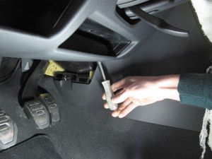
With the included cable set, the FIS-Control is plugged into the CAN gateway. The CAN gateway is located behind the footwell trim, above the brake pedal on the panel to the center console.- Turn off the ignition and pull the key out.
- Remove the footwell trim
- Plug the included cable set between the CAN gateway and the original cable harness.
- Plug the connectors of the cable set into the FIS-Control.
- Socket A: 2-pin plug with black shrinking hose
- Socket B: not used
- Socket C: not used
- Socket D: not used
- Socket E: 4-pin plug with yellow shrinking hose
- Socket F: 2-pin plug with red shrinking hose
- Place the FIS-Control box at a suitable location.
Coding of the instrument cluster / CAN gateway
Normally no coding has to be changed in the car.Compatibility
To be able to send data to the display of the instrument cluster, the FIS-Control uses the CAN bus addresses of the telematics module, or alternatively of the navigation module.As long as there is no navigation system installed that displays guiding directions on the instrument cluster display, that channel is free and can be used by the FIS-Control.
If a navigation system is installed, it has to be checked that the telematics channel can be used. Normally there is no telematics module installed, but not all clusters do support this channel.
Here is a list of the instrument clusters tested so far:
- Part number 8P0 920 930: navigation channel and telematics channel available
- Part number 8P0 920 931: only the navigation channel available
- Part number 8P0 920 932: only the navigation channel available
- Part number 8J0 920 930 G: only the navigation channel available
- Part number 8J0 920 931 F: only the navigation channel available
There are a few 8P/8J that have an engine control unit that speaks UDS instead of KWP2000 (e.g. the 2.0 TDI of 2010). They are not supported by the FIS-Control.
Golf Mk5 platform
Installation
With the included cable set, the FIS-Control is plugged into the CAN gateway. The CAN gateway is located behind the footwell trim, above the brake pedal on the panel to the center console.- Turn off the ignition and pull the key out.
- Remove the footwell trim
- Plug the included cable set between the CAN gateway and the original cable harness.
- Plug the connectors of the cable set into the FIS-Control.
- Socket A: 2-pin plug with black shrinking hose
- Socket B: not used
- Socket C: not used
- Socket D: not used
- Socket E: 4-pin plug with yellow shrinking hose
- Socket F: 2-pin plug with red shrinking hose
- Place the FIS-Control box at a suitable location.
Coding of the FIS-Control
The FIS-Control has to be configured to use the "DDP" channel to communicate with the instrument cluster. As the FIS-Control supports three communication channels to the cluster, a virgin FIS-Control tries one after the other, each time the ignition is started. So you may have to try up to three times to restart the ignition and call the FIS-Control. When the FIS-Control menu gets visible in the cluster, select SETTINGS -> SAVE SETTINGS so that the FIS-Control remembers the working communication channel. Another way to set the communication channel is with the FIS-Control Android app.Coding of the CAN gateway
Sometimes it is needed to enable the item "75 - telematics" in the installation list of the CAN gateway.Compatibility
The FIS-Control works in those cars that are equipped with the full multifunctional display (MFA+). These cars have a red screen in the instrument cluster (Golf Mk5 and Leon 1P) or a white screen (in the case of the Octavia II) that can be controlled either by the buttons of the wiper control stalk or with the buttons of the multifunction steering wheel.Important: The FIS-Control only supports the DDP protocol and not the BAP protocol. Therefore it will not work in the Seat Leon 1P facelift (with the white screen).
FIS-Control
The FIS-Control allows to access a wide range of measurement values and status information of vehicles of the VAG brands (Audi, Volkswagen, Seat, Skoda). The data is shown in real-time on the display of the instrument cluster. The system is controlled by the buttons of the wiper stalk. This way the FIS-Control integrates seamlessly into the car and can be installed perfectly invisible.The focus of development was the fast and accurate monitoring of relevant data, especially of tuned cars: e.g. boost, oil temperature, air-fuel-ratio, exhaust gas temperature.
Many measurement values are already acquired by the stock control units and can be read out by the FIS-Control. Furthermore the FIS-Control has inputs for directly connecting additional sensors.
Supported cars
- Audi A2
- Audi A3/S3 8L
- Audi A3/S3/RS3 8P
- Audi A4/S4/RS4 B5
- Audi A4/S4/RS4 B6 (monochrome and color DIS)
- Audi A4/S4/RS4 B7 (monochrome and color DIS)
- Audi A6/S6/RS6/Allroad C5
- Audi A8/S8 D2 (not all instrument clusters are supported)
- Audi TT 8N (not all instrument clusters are supported)
- Audi TT 8J
- Ford Galaxy WGR
- Seat Alhambra I
- Seat Exeo (OBD not via UDS protocol)
- Skoda Octavia I
- Skoda Superb I
- VW Golf Mk4 / Bora
- VW Golf Mk5 platform
- VW Passat B5 (3B and 3BG)
- VW Sharan I
- VW Transporter T4
The steps of evolution
To extend the feature set and to widen the number of supported cars, there is continuous process of development of the hardware and software of the FIS-Control 2.x.Firmware updates are available for free download on my website www.fis-control.de. The firmware is compatible to all versions of the FIS-Control 2.x. The FIS-Control 1.0 is no longer supported.
FIS-Control 2.0
The FIS-Control 2.0 has the following features:- 32 bit microcontroller
- Interface for 3-wire-bus
- Interface for K-line
- Interface for Infotainment-CAN
- Interface for Diagnosis-CAN
- two serial interfaces (Bluetooth and RS-232)
- Flash memory for data logging
- four relay drivers (for 12V relays)
- seven analog inputs for voltage measurement (0 to 5 volts)
- two inputs for Type-K thermocouples
- Interface for Valentine One radar warner
- integrated ambient pressure sensor
FIS-Control 2.1
In comparison to the previous version there are the following changes:- four of the seven analog inputs have an integrated voltage divider
- additional interface for the Convenience-CAN
FIS-Control 2.2
In comparison to the previous version there are the following changes:- Interface for a second K-line
- switchable pullup resistor for both K-lines
FIS-Control light
The FIS-Control light is the little brother of the normal FIS-Control. The hardware was reduced to only provide the essential features, namely the reading of OBD measurement values and showing them on the cluster screen. The FIS-Control light shares the same code base as the FIS-Control, but of course only the features that are possible with the downgraded hardware can be used.In detail there are the following limitations:
- No 3-wire-bus: The FIS-Control light can only be used in cars where the cluster display can be accessed via CAN bus.
- No sensor inputs: It is not possible to attach any sensors directly to the FIS-Control light. Therefore only the measurement values that can be read out of the control units can be shown.
- L-line is dropped: In the Audi A4 B7 and A6 C5 there is a second diagnosis line for some control units. They can not be reached with the FIS-Control light. In the A4 this are: navigation system, xenon range regulation, radio, TV tuner, tire pressure, trailer, park assist. For the A6: auto HVAC, auxiliary heat, central locks, navigation system, interior monitor, xenon range regulation, radio, tire pressure, park assist.
- No input from the generator: The automatic start of the FIS-Control together with the engine only works if a corresponding CAN bus signal is available (User mod: RPM CAN)
- No integrated ambient pressure sensor: The boost pressure is given as MAP (manifold absolutre pressure) by the engine control unit. To show the relative pressure, the current ambient pressure has to be subtracted. The normal FIS-Control has a precise ambient pressure sensor for this task. The FIS-Control light may subtract a fixed value of "1 bar" instead. Dependent on the real ambient pressure that will lead to inaccuracy.
- No data logging: Unlike the normal FIS-Control, the FIS-Control light doesn't have a dedicated memory to record log files.
- No clear text description of the DTC error codes: The FIS-Control light only shows the error codes of the DTC entries. The normal FIS-Control additionally can show a short clear text description for many of these errors. For the FIS-Control light you will have to search for this info on the internet for example.
- No serial RS-232 interface
- No interface for the Valentine One radar warner
- No relay driver outputs
| FIS-Control 1.0 | FIS-Control 2.0 | FIS-Control 2.1 | FIS-Control 2.2 | FIS-Control Light | |
|---|---|---|---|---|---|
| Display interface | 3 wire bus | 3 wire bus, CAN | 3 wire bus, CAN | 3 wire bus, CAN | CAN |
| OBD interface | K-Line | K-Line, CAN | K-Line, CAN | K/L-Line, CAN | K-Line, CAN |
| Diagnosis protocol | KWP1281 | KWP1281, KWP2000 | KWP1281, KWP2000 | KWP1281, KWP2000 | KWP1281, KWP2000 |
| Bluetooth | no | yes | yes | yes | yes |
| 0-5V sensor inputs | 0 | 7 | 3 | 3 | 0 |
| resistance inputs | 0 | 0 | 4 | 4 | 0 |
| EGT sensor inputs | 0 | 2 | 2 | 2 | 0 |
| relay drivers | 0 | 4 | 4 | 4 | 0 |
| ambient pressure sensor | no | yes | yes | yes | no |
| data logging | no | yes | yes | yes | no |
| DTC descriptions | no | yes | yes | yes | no |
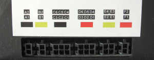
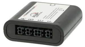
Connectors of the FIS-Control
- A1 - Terminal 31 (ground)
- A2 - Terminal 15 (ignition)
- B1 - K-line
- B2 - Terminal 61
- C1 - Reset button (to cluster instrument)
- C2 - Down button (to cluster instrument)
- C3 - Up button (to cluster instrument)
- C4 - Reset button (from control stalk)
- C5 - Down button (from control stalk)
- C6 - Up button (from control stalk)
- D1 - 3-wire-bus Clock (to cluster instrument)
- D2 - 3-wire-bus Data (to cluster instrument)
- D3 - 3-wire-bus Enable (to cluster instrument)
- D4 - 3-wire-bus Clock (from radio/satnav)
- D5 - 3-wire-bus Data (from radio/satnav)
- D6 - 3-wire-bus Enable (from radio/satnav)
- E1 - Convenience-CAN Low
- E2 - Infotainment-CAN Low
- E3 - Convenience-CAN High
- E4 - Infotainment-CAN High
- F1 - Diagnosis/Powertrain-CAN Low
- F2 - Diagnosis/Powertrain-CAN High
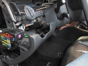
Installation (for example in the Audi A4 B7)
- Turn off the ignition and remove the keys.
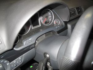
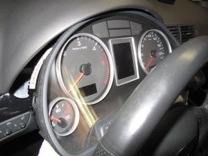
Important: To avoid problems with the immobilizer, don't turn on the ignition while the instrument cluster is disconnected. - Pull the steering wheel to you and push it down as far as possible. So you have more space to remove the cluster. Please put some cloth or towel on the steering column, to avoid scratches on the plastic when removing the cluster.
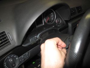
- Remove the cover at the bottom of the cluster. This can be done without tools. Just pull it towards you.
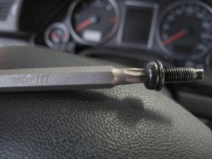
- Remove the two Torx screws.
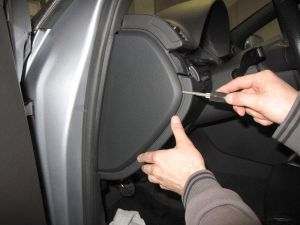
- Remove the side cover of the instrument panel.
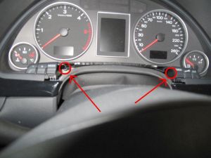
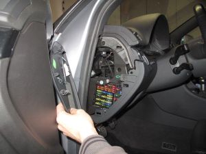
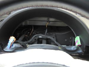
- Now you can reach behind the cluster and push it out to the front.
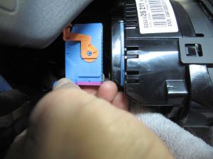
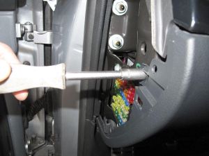
- At the backside of the cluster you will see two 32-pin connectors. To unplug them you can push down the snap-in nose with a screw driver. Now you have to disengage the lever. There might be an additional 4-pin connector. Also unplug it.
- Plug the included cable sets between the cluster and the cluster harness.
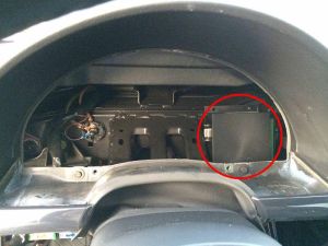
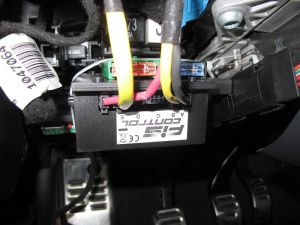
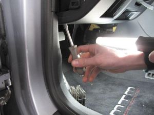
- Find a place to install the FIS-Control main unit. There might be enough space for it behind the cluster or near the fuse panel.
- When installing the main unit under the fuse panel, you have to remove the cover of the driver footwell.
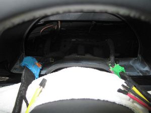
- Depending on the car, the cable set of the FIS-Control consist of either two or three pieces. The connectors that have to be plugged into the FIS-Control main unit are marked with shrinking hose in different colors. The connectors at the FIS-Control box are labeled A to F. The assignment is shown in the following table. The columns represent the color of the connectors at the backside of the cluster and the colors of the shrinking hose of the cable set.
Hint: The blue cable has a yellow marked connector. This connector is not used in all cars. In this case, don't plug it into the FIS-Control. Warning: Don't confuse it with the yellow marked connector of the green cable.
CAN bus or 3-wire-bus?
For VW (except Golf Mk5) and Skoda cars, the FIS-Control only supports the 3-wire-bus to send data to the cluster screen. For some Audis it is possible to use the CAN bus instead. There are a few Audis (A2, some A3 8L, A4 B6, A4 B7, some A6 C5) and the Seat Exeo that don't offer the 3-wire-bus anymore. Only the CAN bus can be used there.On the 3-wire-bus, the FIS-Control behaves like a navigation system. Because it is occupying the bus only as long as it wants to show data on the screen, an installed satnav (with 3-wire-bus) is still able to access the cluster screen and therefore can be used without restrictions.
On the CAN bus, the FIS-Controls sends data like a telematics module would do.
Info: For the VW Golf Mk4/Bora it is not possible to use the FIS-Control if a navigation system or radio is installed that sends data to the cluster screen via CAN bus. 3-wire-bus works fine.
Info: For the Audi A4 (B6/B7) it is not possible to use the FIS-Control when a telematics module is installed. If a telephone module is installed, the FIS-Control can not access the upper two lines of the cluster screen, but the lower part of the screen is usable.
Info: Some older radios that are showing the current radio station via 3-wire-bus on the cluster screen are not compatible to the FIS-Control. As soon as the FIS-Control is installed, they will not be able to show data on the cluster.
If the FIS-Control should be used in 3-wire-bus mode or in CAN bus mode depends on the car and the installed devices. For example, if a satnav is installed that uses the CAN bus to send data to the cluster screen, the FIS-Control should work in CAN bus mode as well.
The FIS-Control automatically detects which bus to use, when the cluster is properly coded.
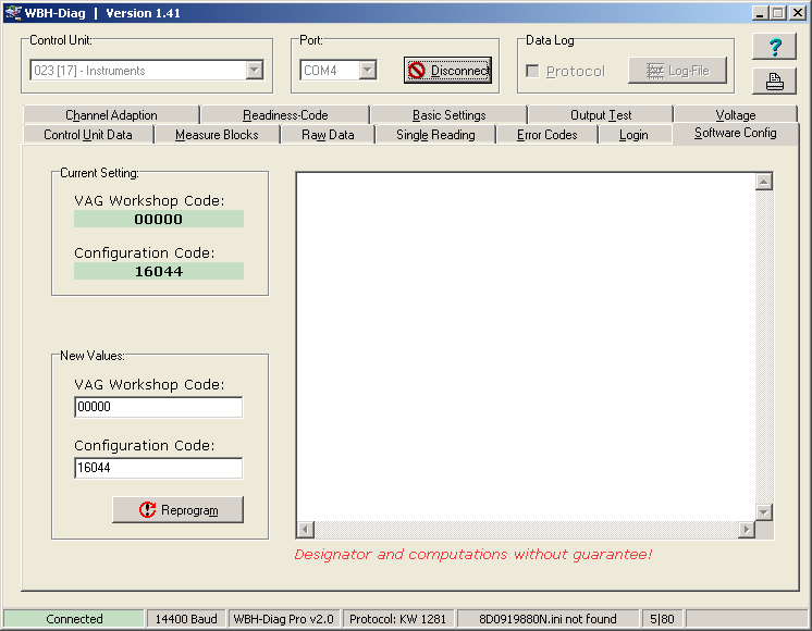
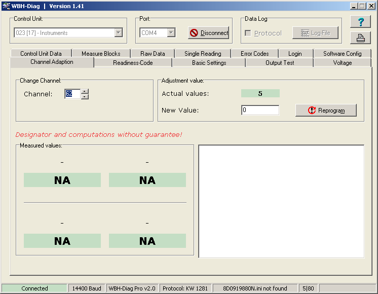
Coding of the instrument cluster
3-wire-bus mode
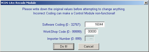
To tell the cluster, that the FIS-Control will send data via 3-wire-bus, the so called softcoding of the cluster has to be changed accordingly. The coding has to be set to a value larger than "16000". If the current value is lower, you have to add "16000" to it.For Audi cars it might be necessary to also change the adaptation channel 62 of the cluster. This channel is the installation list of the devices that are connected to the infotainment CAN of the car. Because no devices shall write data to the cluster via CAN, change the value to "0". For VW cars the installation list often gets updated automatically when the CAN gateway (control unit 19) is recoded with its current value.
Info: If a radio or telephone module is installed, that uses the CAN bus to write to the upper two lines of the cluster screen, you can still keep these devices in the installation list. In this case the devices are still able to show data on the upper part of the screen. The FIS-Control will only use the lower part of the screen.
The coding value for radio is "1", for telephone "2". If both devices are installed, the sum ("3") has to be coded.
CAN bus mode
The FIS-Control identifies itself as a telematics module on the CAN bus. Therefore a telematics module has to be added to installation list of the infotainment CAN. If there is not already a telephone module installed, the FIS-Control can also access the upper two lines of the cluster screen. In this case a telephone module has also to be added to the installation list.The configuration of the installation list is done in the adaptation channel 62 of the instrument cluster.
The coding value is the sum of the device identification numbers:
- 1 = radio
- 2 = telephone
- 4 = navigation system
- 8 = telematics
How to change the coding of the cluster?
The coding of the cluster can be done by a VAG workshop. Or you can do the coding yourself. All you need is a laptop, an OBD-dongle and an OBD software.The FIS-Control can be used as OBD-dongle via its RS-232 interface or via Bluetooth (but only for the K line, not for the diagnosis CAN bus).
With RS-232 it is compatible to VAG-COM (up to version 409.1), VCDS-lite, CarPort and WBH-Diag (up to version 0.89).
With Bluetooth it is compatible to WBH-Diag (above version 1.0) and the Android app Torque Pro (not Torque Lite). Torque only shows the measurement values, but has no option to change the coding of the cluster.
To start the FIS-Control in "OBD-dongle"-mode, press and hold the Up key (for connection via RS-232) or the Down key (for Bluetooth) while turning on the ignition.
The FIS-Control will identify itself as "FIS-CONTROL" when you search for Bluetooth devices. The PIN for bluetooth pairing is "1234".
Info: The Bluetooth module of the FIS-Control is disabled during normal operation. It can only be discovered when it is set to the corresponding mode, like the "OBD-dongle"-mode.
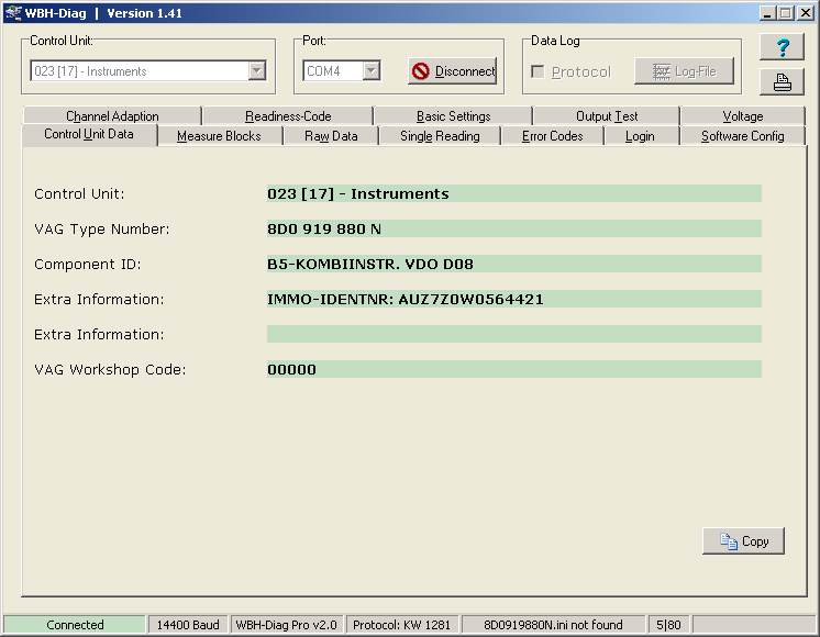
Coding with WBH-Diag
WBH-Diag is available for free from the developer Florian Schaeffer. His website is: https://www.blafusel.de/obd/obd2_wbhdiag.htmlThe software is available in two versions. The older version 0.89 is meant for wired OBD with a serial cable. Therefore you will have to connect the FIS-Control to the RS-232 port of your laptop with a straight serial cable.
The newer versions, WBH-Diag 1.41 and 2.x are working over Bluetooth.
The user interface of both versions is almost identical.
Info: Please use a battery powered laptop in your car.
For wired connection it works best to connect the FIS-Control to a "real" serial port of the laptop. If the laptop does not have a native RS-232 interface, USB-to-serial adapters can also be used. With some of them the connection to the car can be unstable. I had some good experience with cables with FTDI-chipset.
Info: In the program folder of WBH-Diag, there is a configuration file called "wbh-diag.ini". There you can set the language of the tool: "Sprache=de" or "Sprache=en". And you can preconfigure the correct COM-port to use. The splash screen that is shown when the tool is started can be disabled here: "Splash=nein".
After starting the tool, select the Control Unit "023 (17) - Instruments" and choose the correct COM-port.
Now press "Connect".
Coding with VCDS
To check or change the coding of the instrument cluster, press the button "Select" in the main menu of VCDS and choose "17-Instruments" in the list of control units.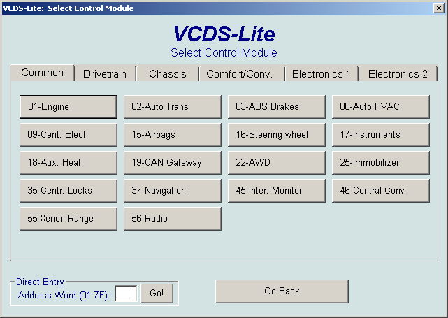
Coding of the FIS-Control
The FIS-Control supports multiple data protocols for communicating with the screens of the instrument clusters.- telematics / 3-wire-bus (this is the default)
- navigation (this can be used when the cluster does not support the telematics channel. This only works when no navigation system is installed)
- DDP (this protocol is used for the Golf Mk5 platform)
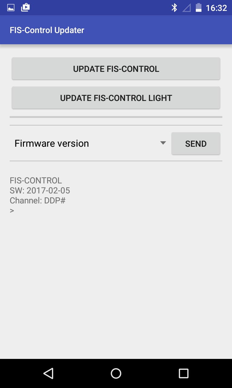
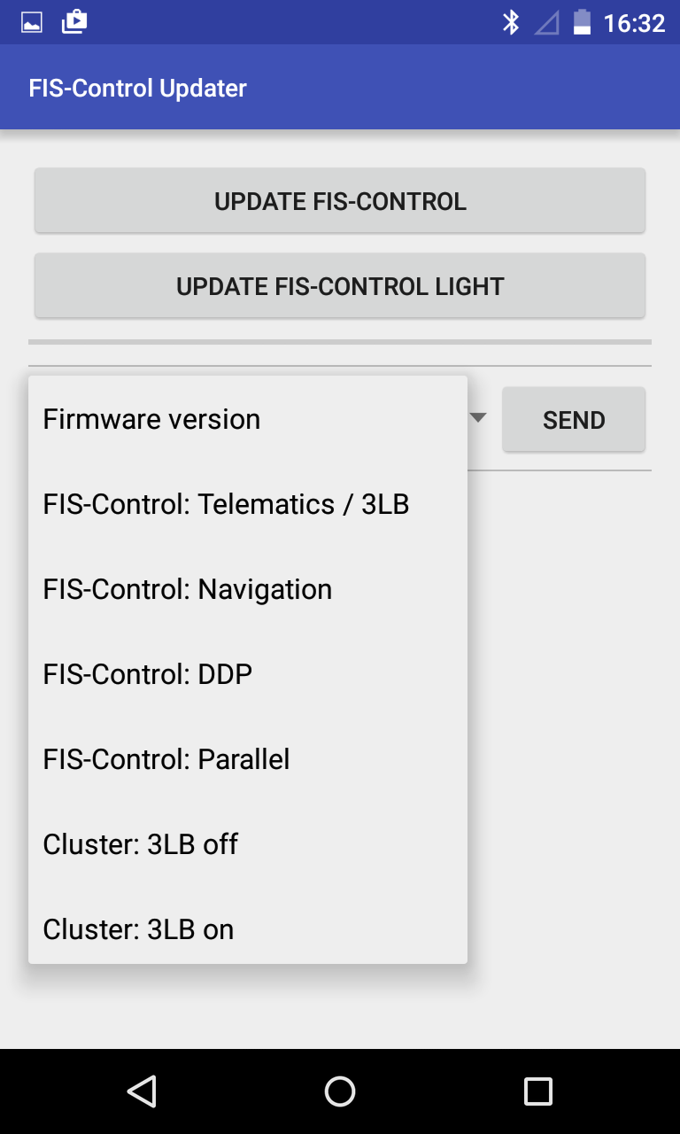
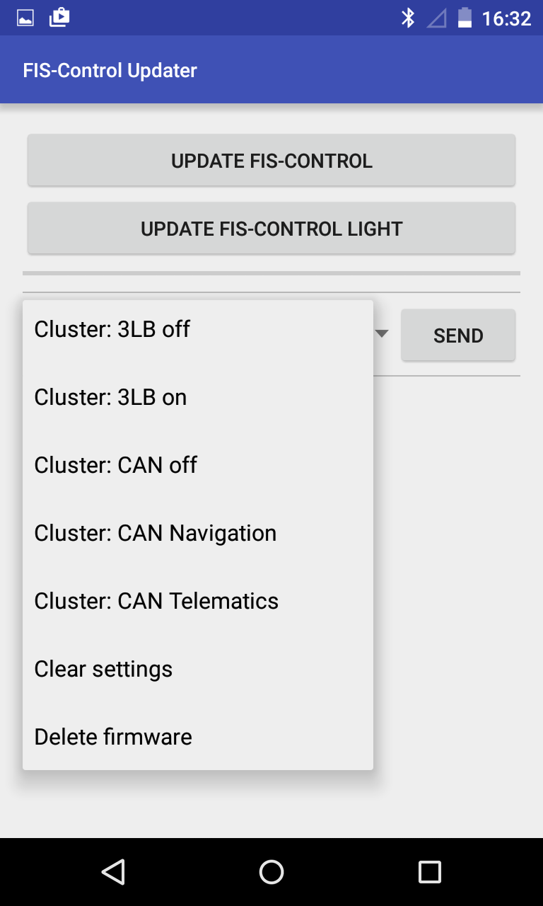
A second way to select the display protocol is to use the FIS-Control Android app. Therefore the FIS-Control has to be set into configuration mode. This mode is activated automatically when the FIS-Control can't communicate with the instrument cluster, or by holding the Down key on the side of the wiper control stalk while turning on the ignition.
In this mode, the FIS-Control can be paired with the Android device via bluetooth. The PIN code is '1234'. In the app you can now select the FIS-Control unit. With the item "Firmware version" in the selection list of the app and SEND you can test that the FIS-Control is connected successfully. If this is the case, you can choose the display protocol for the FIS-Control in the selection list and click SEND to save this settings in the FIS-Control.
For cars where the cluster can be coded via K line, this can also be done here by choosing the appropriate item in the selection list. So you don't need VCDS or WBH-Diag for this.
Configuration of the FIS-Control
The easiest way is to configure all the options of the FIS-Control is with the FIS-Control online configurator.This also allows to label the measurement values and the presets.
Using the FIS-Control
The main menu
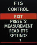
After turning on the ignition, the FIS-Control is in inactive mode by default. This means that you will see the normal board computer in the cluster display. To activate the FIS-Control, do a longpress (about 2 seconds) to the Up key at the side of the wiper control stalk. This will bring up the main menu. You can navigate in the menu with the direction keys (Up key and Down key). To choose an item, press the Select key (that is the Reset key on the bottom of the wiper stalk).When you leave the main menu, the normal board computer will be shown again.
Info: For the Audi A3 8P and Audi A4 B6/B7, the Reset key can not be used by the FIS-Control. Selection of menu items is done by doing a long press on either the Up or Down key.

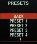
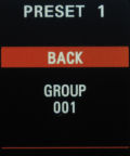
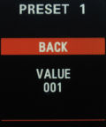
Presets
The preset function is the main function of the FIS-Control. It allows a quick access to the desired measurement values. Every preset is actually one page on the screen that can be configured to show one or more measurement values in a defined view. With the direction keys you can browse through the presets, just like you can do with the values of the standard board computer.The configuration of the preset page is done at "SETTINGS"" -> "PRESETS" (see corresponding chapter).
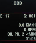
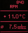
Measurement
With the "MEASUREMENT", any measurement values can be displayed. The values are either read out from a control unit or are measured from sensors that are directly connected to the FIS-Control. A measurement group consists of up to four individual readings. In the first line on the screen, the FIS-Control shows with which control unit it is connected. For example "E: 01" for the ECU 1 (that is the engine control unit). The FIS-Control will read the values from the control unit that is selected at "SETTINGS" -> "CONTROL UNIT", or the control unit that was last used by a preset.Besides the ECU number, the first line also indicates the number of the current measurement group. For example "G: 115" for the measurement group 115. You can browse through the groups with the direction keys.
To display the data from the sensors that are directly connected to the FIS-Control, select the control unit "EXT. SENSORS". The readings from the sensor inputs 1 to 4 are shown in measurement group 1. Inputs 5, 6, 7 and the reading of the ambient pressure sensor that is integrated into the FIS-Control are in group 2. The 3rd group has the values of the two exhaust gas temperature inputs and, if a GPS receiver is connected, the speed and time. The 4th group has some more GPS data: Position (longitude and latitude), altitude and direction.
Info: On some clusters there is a moving dot below the first line of the screen. Each time the FIS-Control updates its data from the control units or the external sensors, the dot will move one step. So the moving dot indicates the refresh rate of the measurement values.
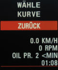
- With "BACK" you can go back to the main menu again.
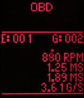
- Pressing the Up key will bring you to a screen which shows the current refresh rate of the readings. 10 FPS for example means, that the FIS-Control gets updated data 10 times per second from the current control unit.
If data logging is enabled, you have to possibility to set a marker here. This allows to identify specific events when analyzing the logs on a PC. Each marker gets a unique number. The number of the latest marker is shown.
Pressing the Down key will bring you back to the measurement screen. - With the directions keys you can select one single value of the current measurement group. This will bring you to three sub-pages that can be browsed with the Down key. To get back to the measurement screen, press the Set key while in the line graph view.
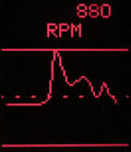
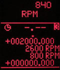
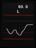
Line graph
"SCALE" (see corresponding chapter in this manual). With the Up key you can change to any of the four configurable scales.Maximum/minimum view / Stopwatch timer
In the maximum/minimum view you will see four lines. The upper and lower line are indicating the currently selected scale settings for the line graph. The two lines in the middle are showing the highest and lowest value that was observed while monitoring the current measurement value. With the Set key, you can reset this view.Like in the line graph view, you can go through the four predefined scales. The corresponding scale values are shown in the up-most and bottom line.
Pressing the Set key also activates the stopwatch timer. The timer is set to "0.00". In this mode, the upper and lower line not longer show the limits of the scale, but the positions of the orientation lines of the line graph that are also the start and stop trigger for the stopwatch timer.
The timer starts running as soon as the current reading crosses the lower orientation line and is stopped as soon as the value reaches the upper orientation line. Therefore the configuration of the timer is actually done by setting the orientation lines of the graph view at "SETTINGS" -> "SCALE".
Tip: Even when the stopwatch timer is activated in the max/min view, it still stays active in the other views. So you can browse to the line graph view and watch the current value.
Board computer view
The board computer view shows the currently selected measurement value in the upper segment of the cluster screen, while the middle segment is free for the normal board computer. With the Up and Set key the board computer can be operated as usual, while the Down button will bring you back to the line graph view.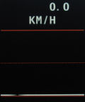
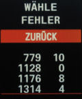
Read DTC
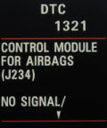
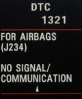
Here you can read out the diagnostic trouble codes (DTC) of the currently selected control unit. Up to four errors are shown on each page. With the direction keys you can browse the pages.Every error code consists of two numbers. The first one is the identifier for the error itself. The second gives additional information. An asterisk behind the code tells, that this is not a permanent but a sporadic error.
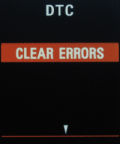
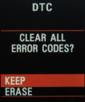
To leave the DTC list, press the Set key. Now you can either select "BACK" to go back to the main menu, or you can select one of the error codes to get a description of the error code. Pressing the Up key instead will bring you to a menu where you can clear the error codes of the current control unit.
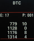
Info: Some control units only show one error on each page.
Settings
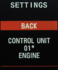
Control unit
Here you can choose the ECU from which you want to read measurement values via OBD, or if you want to have the readings of the sensors that are connected directly to the FIS-Control ("EXT. SENSORS"). All control units are listed twice. If there is no asterisk behind the ECU number, then the FIS-Control will use the K-line to communicate with the ECU. If there is an asterisk, the FIS-Control will use the CAN bus instead. The most interesting readings will come from the engine control unit. This has the number "1" or "1*". Of course you can select any of the ECU numbers. Most of them, but not all, have labels.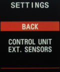
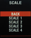
Scale
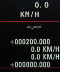
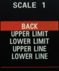
To use the functions "line graph" and "stopwatch timer" during a measurement, a scale has to be configured first. For example if you want to line graph the boost pressure, you can set the "UPPER LIMIT" of the scale to match the highest expected pressure. The values are always in the unit in which they are displayed. If you expect a boost pressure of up to 2500 mbar, set the "UPPER LIMIT" to "+002500.000" (the point is a decimal point). If the boost pressure is shown in Bar instead, enter "+000002.500".With the direction keys you can change the sign or digit at the cursor position of the number. The cursor is moved with the Set key.
With "UPPER LINE" and "LOWER LINE" you can add to dotted orientation lines to the line graph view.
Info: If the lower orientation line is set to the same value as the lower limit, this will give a solid line instead of a dotted one. This is helpful for displays that don't show a lower borderline by themselves.
Info: If only want one or no orientation line visible on the screen, you can place it outside of the scale, for example to the value "-999999.999".

Presets
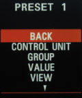
- Control unit
Here you can choose the ECU from which you want to read measurement values via OBD, or if you want to have the readings of the sensors that are connected directly to the FIS-Control ("EXT. SENSORS"). All control units are listed twice. If there is no asterisk behind the ECU number, then the FIS-Control will use the K-line to communicate with the ECU. If there is an asterisk, the FIS-Control will use the CAN bus instead. - Group
Select the measurement group that has the desired reading. - Value
A measurement group holds up to four values. Dependent of the selected view, only one of them is shown. Here you can select which one it is. - View
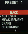

- Not used: this preset will not be shown and is skipped when browsing the presets
- Measurement: all values of the selected measurement group are shown at once
- Graph: The selected measurement value will be plotted as line graph. The corresponding scale for the graph can be set in the second page of the preset configuration.
Info: If the lower orientation line is set to the same value as the lower limit, this will give a solid line instead of a dotted one. This is helpful for displays that don't show a lower borderline by themselves. - Board-computer: The selected reading will be shown in the upper segment of the cluster screen. The standard board-computer will be seen in the middle segment.
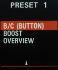
- B/C (button): This view is identical to the board-computer view, but the board computer can still be controlled with the Down key. Therefore it is only possible to navigate upwards through the presets.
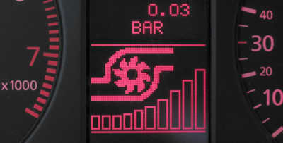
- Boost: A bar graph and the symbol of a turbo charger will be shown. The scale of the bar graph is set with the "upper limit" and "lower limit" on the second page of the preset configuration.
- Overview: A selection of readings is shown (speed, RPM, coolant temperature, oil temperature, tank capacity, turbo boost, intake air temperature, torque), Beside the boost pressure, all readings are taken from the powertrain CAN bus.
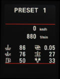
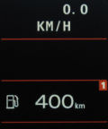
Info: To show the correct turbo boost pressure, you have to tell the FIS-Control, where to find that value ("CONTROL UNIT", "GROUP", "VALUE"). Additionally you should configure the boost display at "SETTINGS" -> "BOOST" to show the unit "BAR" or "PSI" and the "GAUGE" scale. - Single value: A selected reading is shown in the middle segment of the screen.
- Collection: A collection of up to six readings is shown. Unlike the other views, it is possible to build the collection of readings from different measurement groups of one control unit. Additionally it is possible to also show measurements from sensor that are directly connected.
Save settings
All changes that are done in "SETTINGS" are only valid until you turn off the ignition. If you want to save them permanently, select "SAVE SETTINGS". Now the settings will be loaded again, when the ignition is turned on.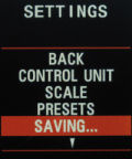
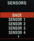
Sensors
The FIS-Control offers inputs for several sensors.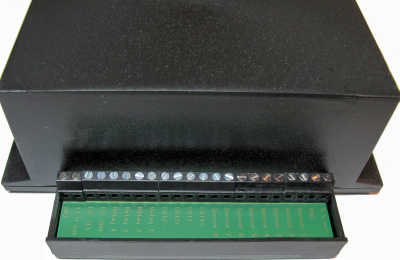
- 5 volts (Warning: Don't connect power consumers! This is to supply the ratiometric sensors only.)
- GND (ground for the sensors)
- Sensor 1 (analog input with integrated 1.1 kOhm voltage divider)
- Sensor 2 (analog input with integrated 1.1 kOhm voltage divider)
- Sensor 3 (analog input with integrated 220 ohms voltage divider)
- Sensor 4 (analog input with integrated 220 ohms voltage divider)
- Sensor 5 (analog input, 0-5 volts)
- Sensor 6 (analog input, 0-5 volts)
- Sensor 7 (analog input, 0-5 volts)
- Sensor 8 (digital input)
- EGT1+ (positive input for the first EGT sensor)
- EGT1- (negative input for the first EGT sensor)
- EGT2+ (positive input for the second EGT sensor)
- EGT2- (negative input for the second EGT sensor)
Configuration of the sensors
Up to seven analog sensors can be connected to the FIS-Control. The FIS-Control has an 8-channel analog/digital-converter with a voltage range from 0 to 5 volts. Input 8 is internally connected to an ambient pressure sensor.Info: For hardware version 2.0, sensors that have a changing resistance instead of a signal voltage can not be connected directly to the FIS-Control. A separate voltage divider will be needed to interface such sensors. I can give a more detailed explanation on request.
Info: Starting with hardware version 2.1, the FIS-Control has integrated voltage dividers for the first four sensor inputs. This allows to directly connect sensors that have an output resistance instead of an output voltage.
Inputs 1 and 2 have an internal voltage divider with an 1.1 kOhms resistor. Inputs 3 and 4 have a voltage divider with 220 ohms.
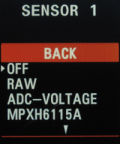
In the settings menu of the FIS-Control you can choose the characteristic curves of some typical sensors. Missing sensors can be added by me. Just ask.
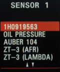
The following sensors are already supported:
- Type-K thermocouple (please use input EGT1 or EGT2)
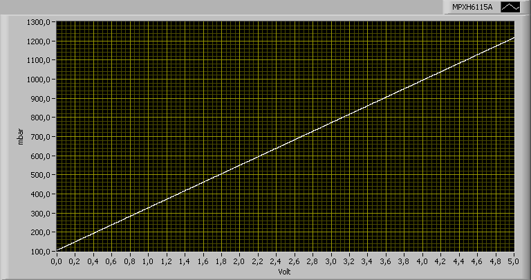
- Boost pressure sensor Freescale MPXH6115A
- Oil temperature sensor VAG 1H0 919 563 (connect to voltage divider with 1.1 kOhms)
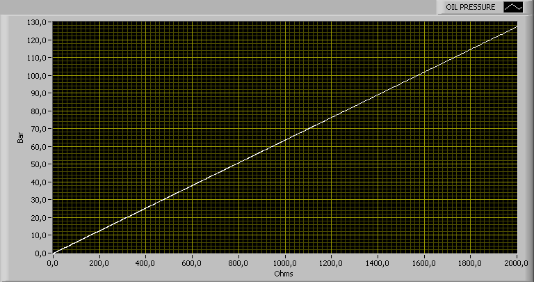
- Oil pressure sensor (connect to voltage divider with 220 ohms)
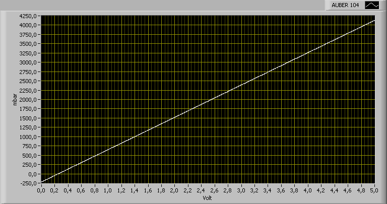
- Boost pressure sensor Auber 104
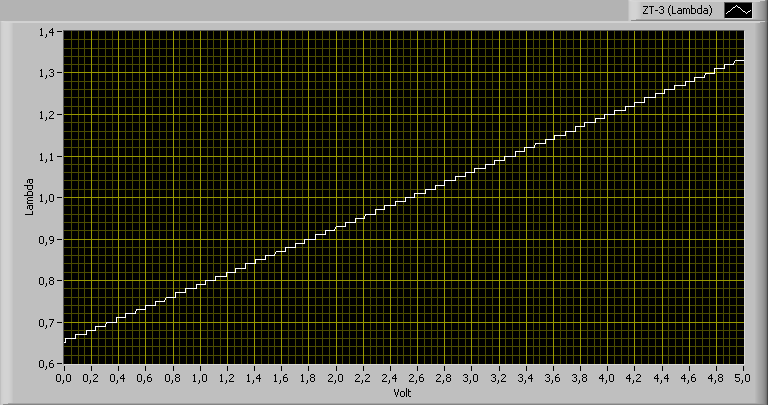
- Wide band lambda Zeitronix ZT-2 / ZT-3
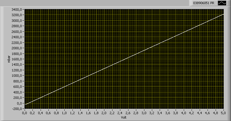
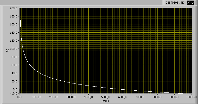
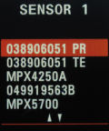
- Boost pressure sensor vom VAG 038 906 051
- Intake air temperature sensor of the VAG 038 906 051 (connect to voltage divider with 1.1 kOhms)
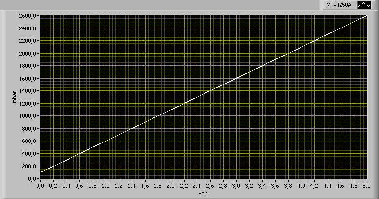
- Boost pressure sensor Freescale MPX4250A
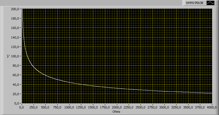
- Oil temperature sensor VAG 049 919 563 B (connect to voltage divider with 1.1 kOhms)
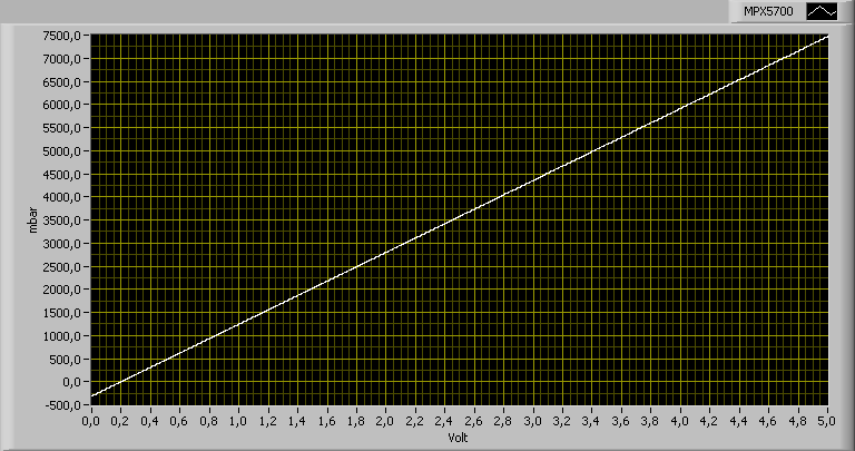
- Boost pressure sensor Freescale MPX5700
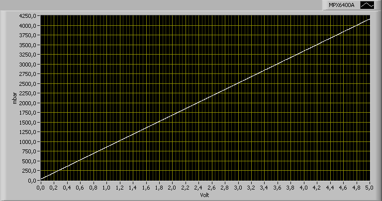
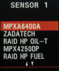
- Boost pressure sensor Freescale MPX6400A
- Boost pressure sensor Zadatech (Hint 1: This sensor needs a power supply of 12 volts. Hint 2: This sensor already gives a relative boost pressure. It is not needed that the FIS-Control subtracts the ambient pressure, so set SETTINGS -> BOOST -> SCALE to ABSOLUTE)
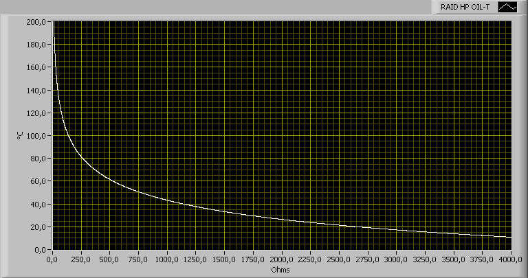
- Oil temperature sensor Raid HP (connect to voltage divider with 1.1 kOhms)
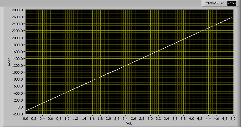
- Boost pressure sensor Freescale MPX4250DP
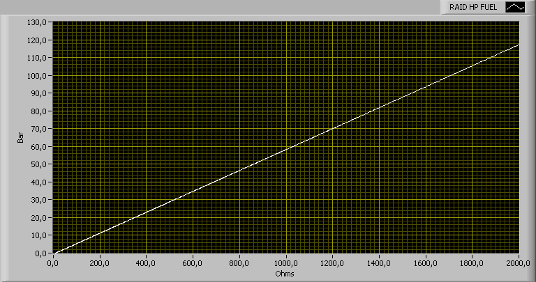
- Fuel pressure sensor Raid HP (connect to voltage divider with 220 ohms)
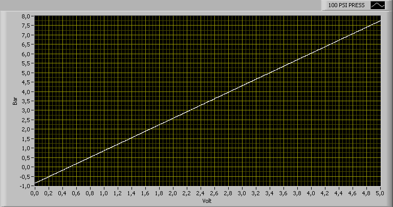
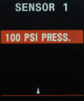
- 100 PSI pressure sensor
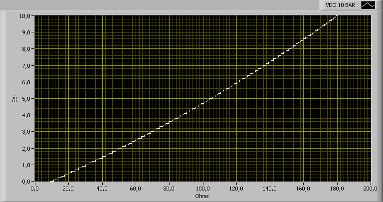
- VDO 10 Bar pressure sensor (connect to voltage divider with 220 ohms)
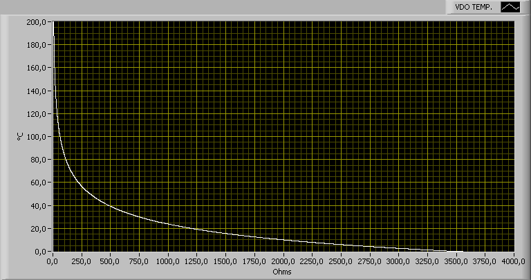
- VDO temperature sensor (connect to voltage divider with 1.1 kOhms)
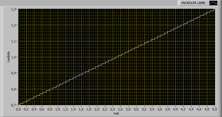
- Knoedler lambda sensor
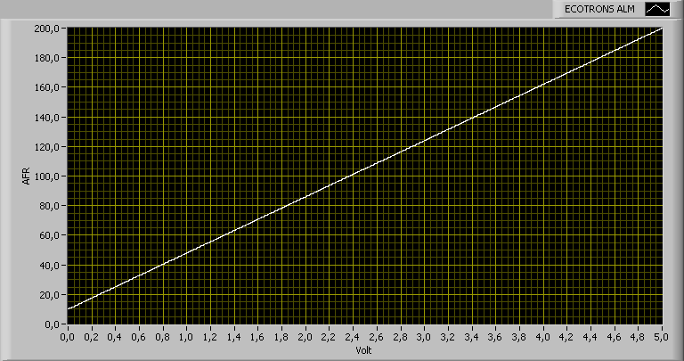
- Ecotrons ALM
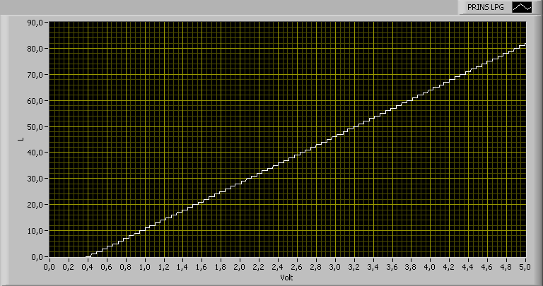
- Prins LPG
- Zeitronix ECA-2
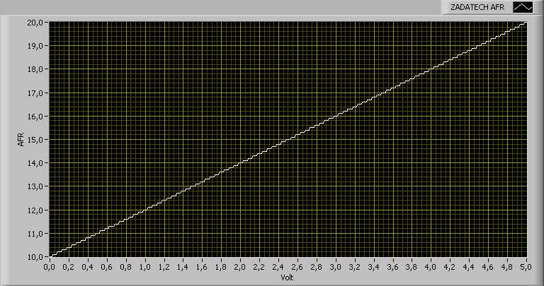
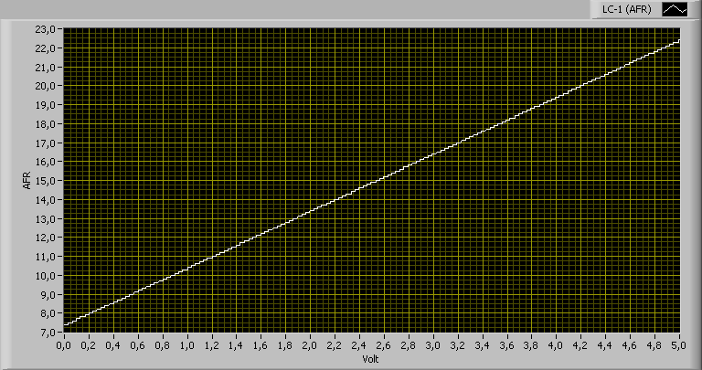
- Zadatech AFR (Important note: The current version of that sensor has a different output signal. It is now identical to the Innovate LC-1, so select the LC-1 in the FIS-Control also for the Zadatech AFR sensor.)
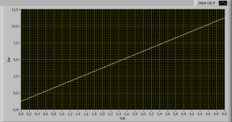
- Zadatech oil pressure
- Zadatech oil temperature (connect to voltage divider with 1.1 kOhms)
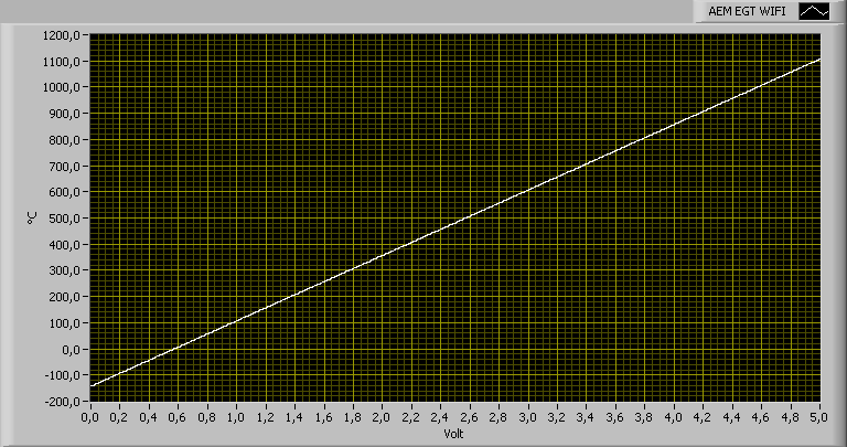
- AEM EGT WiFi
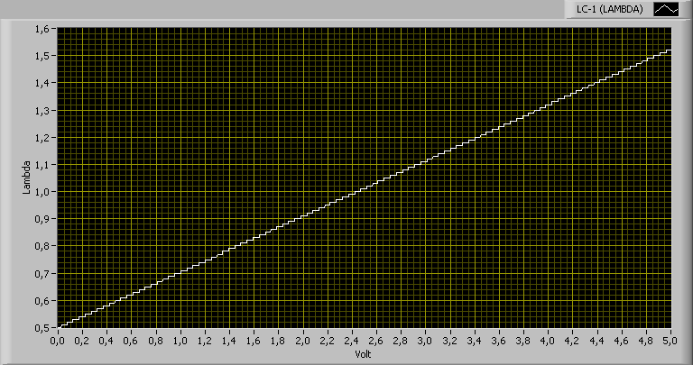
- Innovate LC-1
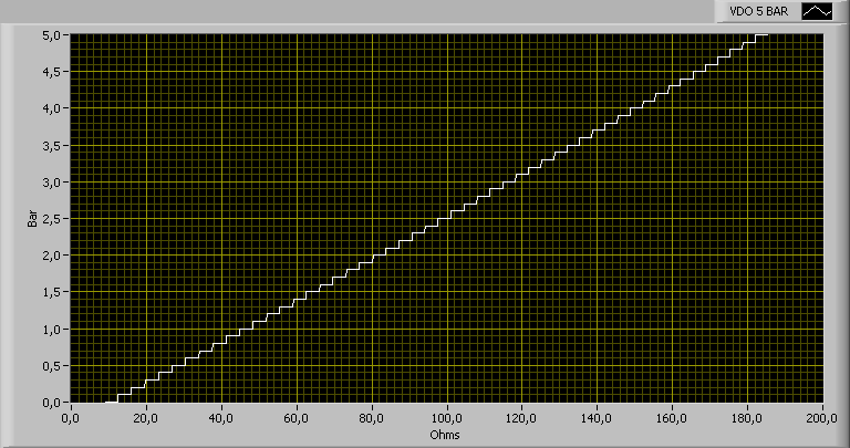
- VDO 5 Bar pressure sensor (connect to voltage divider with 220 ohms)
- PLX AFR sensor
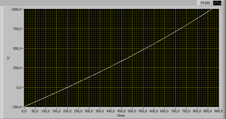
- PT200 (connect to voltage divider with 1.1 kOhms)
- 60 PSI pressure sensor
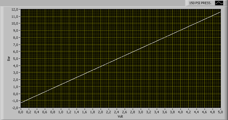
- 150 PSI pressure sensor
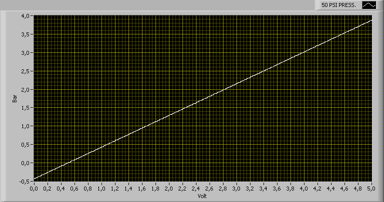
- 50 PSI pressure sensor
- 75 PSI pressure sensor
- Zadatech Lambda
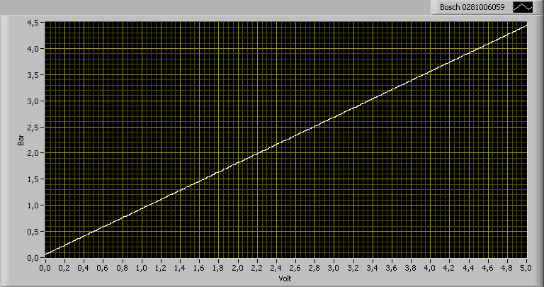
- Bosch 0281006059
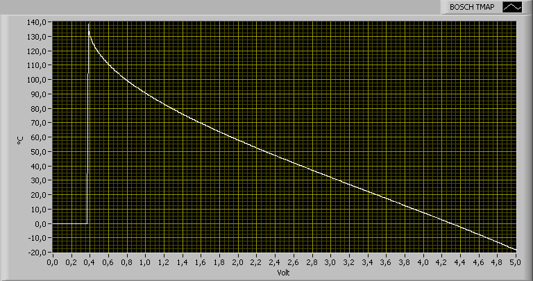
- Bosch 3 Bar TMAP
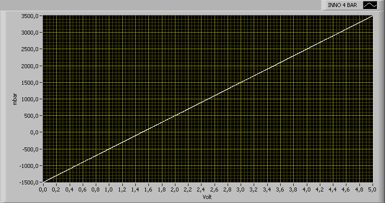
- Innovate 4 Bar MAP
- ZEITRONIX 50 PSI
- MPXH6300A
- 30 PSI PRESS.
- PLX 150 PSI
- 200 PSI PRESS.
- BMW PRESS.
- AEM 30-0300
- Boost pressure sensor Freescale MPXH6115A
- Oil temperature sensor VAG 1H0 919 563 (connect to voltage divider with 1.1 kOhms)

- Oil pressure sensor (connect to voltage divider with 220 ohms)
- Boost pressure sensor Auber 104
- Wide band lambda Zeitronix ZT-2 / ZT-3

- Boost pressure sensor vom VAG 038 906 051
- Intake air temperature sensor of the VAG 038 906 051 (connect to voltage divider with 1.1 kOhms)
- Boost pressure sensor Freescale MPX4250A
- Oil temperature sensor VAG 049 919 563 B (connect to voltage divider with 1.1 kOhms)
- Boost pressure sensor Freescale MPX5700
- Boost pressure sensor Freescale MPX6400A
- Boost pressure sensor Zadatech

- Oil temperature sensor Raid HP (connect to voltage divider with 1.1 kOhms)
- Boost pressure sensor Freescale MPX4250DP
- Fuel pressure sensor Raid HP (connect to voltage divider with 220 ohms)
- 100 PSI pressure sensor
- VDO 10 Bar pressure sensor (connect to voltage divider with 220 ohms)
- VDO temperature sensor (connect to voltage divider with 1.1 kOhms)
- Knoedler lambda sensor
- Ecotrons ALM
- Prins LPG
- Zeitronix ECA-2

- Zadatech AFR
- Zadatech oil pressure
- Zadatech oil temperature (connect to voltage divider with 1.1 kOhms)

- AEM EGT WiFi
- Innovate LC-1
- VDO 5 Bar pressure sensor (connect to voltage divider with 220 ohms)
- PLX AFR sensor

- PT200 (connect to voltage divider with 1.1 kOhms)
- 60 PSI pressure sensor

- 150 PSI pressure sensor
- 50 PSI pressure sensor
- 75 PSI pressure sensor

- Zadatech Lambda

- Bosch 0281006059
- Bosch 3 Bar TMAP
- Innovate 4 Bar MAP
Info: For precise and reliable measurements, the sensor ground should be equal to the GND of the FIS-Control. Some sensor are using the chassis to connect to ground. In this case, it could be a good idea to have a separate ground wire from the FIS-Control to a GND near the sensor. Please make sure, that no high currents can go over this wire. This could happen, for example when the ground connection to the engine block fails.
Info: Don't use extension cables for the signal wires of the Type-K thermocouples to avoid measurement errors.
Displaying the sensor measurements
To select the sensors, choose "Control unit 0". Like for other measurement groups, the sensor values are packed in groups to up to four values each. Group 1 has the measurement values of the first four sensor inputs. Group 2 has the sensor 5 to 7 and the internal ambient pressure sensor. In group 3 are the two exhaust gas temperature sensors.Features and using of the sensors is like for the OBD control units.
So it is also possible to use the "boost option" that allows to convert the boost reading from absolute to gauge boost.
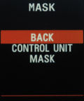
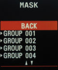
Mask
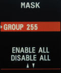
In principle every control unit can have up to 255 different measurement groups. Most of them are not used, though, or have readings that are not of interest. During a running measurement, you can browse through the measurement groups with the direction keys. To not waste time browsing all measurement groups, you can hide the ones that are not of interest for you.First select the control unit for which you want to hide groups. Now you can go to the menu item "MASK". There you can either make a group visible (checkmark set) or hide it (checkmark not set). At the end of the list, there are two options to enable or disable all measurement groups of the current control unit at once.
Hint: If you disable all groups of a control unit, the whole control unit will be invisible in many control unit lists. So if you spend the time to hide all unneeded control units and measurement groups, this will make it more comfortable to use the FIS-Control from then on.
Hint:Often it is easier to disable all control units and then only enable the ones that are installed. To do this, choose one of the control units and click three times on "DISABLE ALL" in the mask list. Now all control units are hidden. To enable a control unit again, select it and change its mask settings, for example by disabling and enabling one group of it.
Hint: To distinguish between enabled and hidden control units, the control unit number of hidden control units is set in braces.
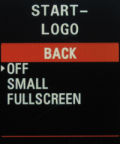
Startlogo
The FIS-Control can show a customizable welcome screen when turning on the ignition. For clusters with the monochrome screen, you can create the startlogo yourself and copy it to the FIS-Control. For the color screens there is a collection of logos available at https://fis-control.de/startlogos/. More startlogos can be created on request.In the settings menu you can pick one of nine monochrome logos. But first these logos have to be provided. There is a windows tool that allows to generate the collection of startlogos.
First the startlogos have to be created. You can either load some templates from the internet or draw your own, for example with Paint. The images have to have a resolution of 64x88 or 64x48 pixels and have to be stored in the TIFF format.
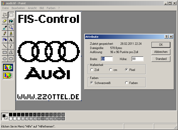
First select one empty slot on the left, then choose a valid TIFF file with a startlogo. A preview of the logo will be shown. When you added your logos to the collection, you can "Save file". The filename doesn't matter. Just remember where you saved the file.
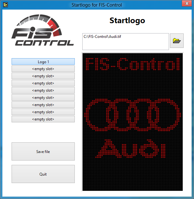
Info: There are a few clusters out there that will not show the startlogo right away. Often this can be solved by setting a delay time before the FIS-Control tries to display the logo. The delay time can be set in the settings menu of the FIS-Control. Select "Tweaks" and set a "Logo delay" in milliseconds.
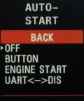
Autostart
After turning on the ignition, the FIS-Control is inactive by default. A longpress to the Up key will bring you to the main menu of the FIS-Control and allows to start actions from there.The autostart feature allows to directly load the "PRESET 1" instead of the main menu, if you set it to "BUTTON".
Additionally there is the option "ENGINE START". With this enabled, the FIS-Control will launch the "PRESET 1" automatically when the engine is started.
Info: Precondition for the autostart feature is a valid configuration of Preset 1. For some cars it is needed to enable the user mod "RPM CAN".
With the setting "UART<->FIS" the FIS-Control directly enters a mode where you can send data over the RS-232 of the FIS-Control to the cluster screen, e.g. with a CarPC.
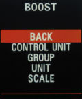
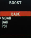
Boost
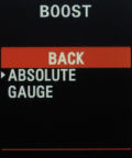
The control units in VAG cars typically don't measure the actual boost pressure, but the MAP (manifold absolute pressure). To get the boost pressure like normal boost gauges are showing it, the ambient pressure (about 1 Bar) has to be subtracted from the MAP reading. The FIS-Control can do this. Therefore it has an on board ambient pressure sensor.In the settings menu is the item "BOOST". Here you can select the control unit that provides the MAP reading (usually the engine control unit) and in which measurement group the value is found. The pressure is displayed in the unit "mbar" by default, but this can be changed here to BAR or PSI. With the scale option you can choose if the value shall be shown as absolute or relative (gauge) pressure.
Headline
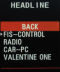
The headline is the upper two text lines of the cluster display. The FIS-Control uses the headline mainly to show the title of the current menu. Therefore the headline is expendable in most cases. Instead you can have the output of your radio or the telephone (if they are sending this data via CAN bus to the cluster). The both text lines can also be used to display data from a Car-PC that is connected to the FIS-Control via RS-232. (For more info about this, please write me an email).Additionally it is possible to use the headline as monitor for the "Valentine One" radar warner. The FIS-Control provides an RJ11 jack where you can plug the cable of the V1. The FIS-Control is also the power supply for the radar warner.
Info: In cars equipped with a telephone module, this module occupies the headline of the cluster screen permanently (even when it doesn't show actual data there). When the FIS-Control also sends data to the headline, you will see a flickering, because the display switches between the data from the telephone module and the FIS-Control quickly. The headline can not be used in this case. To stop the FIS-Control from sending data to the headline, select the item "RADIO".
Flash memory
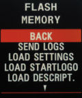
The FIS-Control has an on board memory chip to store the user settings, the descriptions of the DTC error codes, the startlogos (only the ones for the monochrome cluster display). Also it can log all measurement values here when data logging is active.At "SETTINGS" -> "FLASH MEMORY" it is possible to transfer data between the flash memory of the FIS-Control and a PC via RS-232 or Bluetooth.
With "SEND LOGS" you can send the logged measurements to the PC.
With "SEND SETTINGS" and "LOAD SETTINGS" the configuration of the FIS-Control can be exported to a PC via XModem protocol and imported from it. With the online configurator it is possible to edit the configuration file:
https://fis-control.de/config_en.html
Important: After uploading the settings file, don't select "SETTINGS" -> "SAVE SETTINGS". The new configuration gets active automatically next time the ignition is switched on.
With "LOAD STARTLOGO" you can bring own startlogos to the FIS-Control.
With "LOAD DESCRIPTIONS" you can load the clear text descriptions of the DTC error codes to the FIS-Control. The needed file is available on my website.
With "FACTORY RESET" you can clear the whole flash memory of the FIS-Control. This will delete all user settings, startlogos, error descriptions and logs.
The erase process will take about one minute.


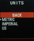
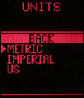
Units
The control units are normally using the metric unit system for their readings.But you can also choose imperial or US unit system. The FIS-Control will convert the readings accordingly.
So liters will be gallons, kilometers will be miles and Bar will be PSI.
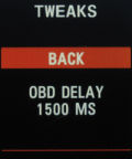
Tweaks
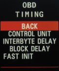
The communication protocol in the car is time critical. The FIS-Control uses default values that should be working without problems in most cars. At "SETTINGS" -> "TWEAKS" you can adjust some timing values. This can be needed, if an OBD connection with a control unit is too slow or unstable.At "OBD TIMING" are two values that can be set.
Interbyte Delay
This is the delay between each byte that the FIS-Control sends over die diagnosis wire. This value is only relevant for control units that are using the KWP1281 protocol. The unit is "tenth of milliseconds". The default value is "50", so there is a delay of 5 milliseconds before sending a new byte. Some control units don't need any delay at all, this can improve the communication speed, so that the FIS-Control can read new measurement data more often.Block Delay
This is the delay in milliseconds, that the FIS-Control uses before sending a new command on the diagnostic wire. Most control units with KWP1281 don't need a delay here. For control units with KWP2000 this is different. They are telling the FIS-Control a delay time that should work. Although the FIS-Control uses the given delay time, some connections are not stable. So you can set a block delay time here, that overrides the timing. A block delay of 85 milliseconds has proved as working and should be set for all control units with KWP2000.The block delay is also relevant for the measurement of the external sensors, that are directly connected to the FIS-Control. If you select "EXT SENORS" as control unit, you can set the delay between two measurements. If you want to read the sensors 10 times per seconds, set the delay to 100 milliseconds.
Fast Init
This option shortens the time for establishing a new connection to a control unit about one second. This helps when browsing through presets with different control units, because every time the control unit is changed, a connection has to be closed and a new has to be established.Some control units do not support fast init. If you have problems when connecting to a control unit, disable the fast init option.
OBD delay
When browsing through presets that are reading data from different control units, the FIS-Control has to close and open an OBD connection each time. There has to be an idle time between two connections. This time can differ between control units, so you can configure it here. Short delays allow faster browsing through the presets, longer delays are more stable.Info: The FIS-Control does more than one attempt to connect to a control unit in case the first connection fails. If the OBD delay is set too short, it is possible that the FIS-Control has to try many times before it can connect to the control unit. This may take longer as if a longer delay was set that works on first try.
The number of attempts can be seen in the main menu when selecting "ECU INFO".
Logo delay
When the startlogo feature is enabled, the FIS-Control tries to send the startlogo to the cluster as soon as the ignition is turned on. Some clusters don't accept data at this time. Often it helps to just wait a few milliseconds before sending the logo. This delay can be set here.Alternative bar graph
The preset view "boost" shows a bar graph. The bars are filled dependent of the current boost pressure. For some cluster, this works only when the "ALT. BAR GRAPH" is selected.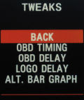
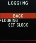
Logging
During an active measurement, the FIS-Control can log all measurement values to its internal memory. The memory is designed to hold a few days, up to some weeks of data. If the memory is filled completely, the oldest data is overwritten by the new data.Following data is logged:
- Timestamp
- OBD data (if an OBD measurement is active)
- Current values of all connected sensors
The loggings are splitted into single sessions. A new session is started automatically when the logging is enabled in the settings menu, or (when permanent logging is enabled) as soon as the ignition is switched on.
To manually start a new session, it is possible to disable and re-enable the logging in the settings menu.
The current time and date is assigned to each logging session. Therefore you have to set the clock first. This can be done in the logging menu. To keep the clock running even when the ignition is switched off, you have to insert a coin cell battery into the FIS-Control (type CR1220 3V).
During an active logging session, it is possible to set markers. This makes it easier to find events in the logfile later.
To set a marker, you have to go to the measurement group view of the current measurement. Now press the Set key to enter the page with the selection for single values. Instead of choosing a single value, press the Up key to open an additional menu page. There is the item "SET MARKER". Also there is a counter for the markers. The number of the just set marker is shown.
The logfiles can be transferred to a PC using RS-232 or bluetooth. In the settings menu there is the submenu "FLASH MEMORY" with the option "SEND LOGS". Here you can select the logging sessions you want to transfer. Now click "SEND".
On the PC side you have to start a tool that supports file transfer via XModem protocol, e.g. HyperTerminal.
Some tools allow to define the XModem protocol in more detail. For the transfer of the logfiles, the FIS-Control uses "1K-XModem with CRC".
The logfile can be saved with any name.
The tool "logfile-converter" that is provided on my website will convert the received logfile into CSV format. CSV-files can be opened with Microsoft Excel or OpenOffice Calc.
GPS Mouse
You can connect a GPS receiver to the RS-232 port if the FIS-Control. All GPS receivers with an RS-232 interface that are using the NMEA0183 protocol are compatible. Usually the baudrate for the NMEA protocol is 4800. Other baudrates can be configured in the FIS-Control.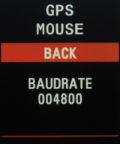
User mods
I included some features and modifications that were requested by single users. Because those features are not relevant for most users, they are disabled by default. Please enable them only, if you know what they are doing.To prevent accidental activation, the features will not get active immediately when they are selected. You first have to save the settings and switch the ignition off and on again.
These feature are included:
- oPDC In the Audi A4 B7 the CAN messages from the PDC control unit are forwarded from the powertrain CAN to the infotainment CAN, so that the RNS-E can receive them. When a new RNS-E is installed, it is possible to use the optical PDC now.
- Engel The relays 1 and 2 are always switched at the same time.
- Juha After engine start, the relay 1 is automatically switched on.
- Auber The FIS-Control calculates an moving average of the values from the Auber 104 boost pressure sensor to get a smoother graph.
- Nico The voltage dividers of the sensor inputs are using different resistors.
- Separator Instrument clusters with color DIS will show a divider line on the overview preset.
- L-Line A4 Some control units of the A4 B7 can only be reached via L line. To access them with the FIS-Control, the screw terminal "L-Line" has to be connected with pin 15 of the OBD socket.
- L-Line A6 Some control units of the A6 C5 can only be reached via L line. To access them with the FIS-Control, the screw terminal "L-Line" has to be connected with pin 15 of the OBD socket.
- AVF Boost Engines with the engine code "AVF" are sending the boost pressure without a unit. To allow the FIS-Control to identify that reading as boost. the item "AVF boost" has to be enabled.
- B6 cluster Workaround for some issues with the B6 instrument clusters with monochrome DIS.
- Trasky The menu items SETTINGS and RELAYS are exchanged.
- Demo The FIS-Control runs ins a demo mode.
- Schwind Overview screen modified for a user.
- Skols Calculation of one OBD reading changed for a user
- oPDC B6 For the Audi A4 B6 the CAN message of the PDC control unit are forwarded from the powertrain CAN to the infotainment CAN and therefore to the RNS-E. This allows to retrofit a newer RNS-E and use the optical PDC functionality.
- RPM CAN The FIS-Control uses the RPM signal from the CAN bus to trigger the automatic start of the FIS-Control.
- RFK The FIS-Control generates all needed CAN messages to use the rear view camera of an Audi R8 in the Audi A4.
- RFK Diag This will forward the OBD message from the OBD port to the rear view cam control unit.
- Slow Overview The refresh rate of the overview screen is reduced to 5 fps. Also the RPM is rounded.
- MAP Factor MAP reading is modified to fit a tuned engine control unit of a user.
- Enrico Overview screen modified for an user.
- Hrdina Autostart is triggered with ignition, not engine start.
- 3 Button The FIS-Control uses also the set key of the wiper control stalk.
- Pflieger Show oil pressure of external sensor instead of torque in the overview.
- TT Cluster Fixes some problems when drawing graphics for the TT 8N instrumenr clusters.
- AFR Converts the OBD values for lambda to AFR.
- Wiper Helps that the boardcomputer is not changed unintentionally when the wiper control stalk is used in the BC presets.
- Jentz The buttons of the multifunction steering wheel can be used (an additional CAN bridge has to be installed).
- Digits All values are shown with one decimal place.
- Kerry Converts the unit from some pressure parameters to PSI.
- MAP Scale 2x MAP reading is modified to show double the value.
- CAN-Bridge Can be used with the modified firmware of the RNS-E to show the guidance on the cluster screen.
- Turbodrive Shows parameters from the Turbodrive ECU.
- Big Speed Shows the vehicle speed in the overview screen with a larger font (only for the color FIS in the A4)
- Tiptronic Use the Tiptronic buttons on the multifunction steering wheel of the A4 B6 to control the FIS-Control.
- Digital In Use the sensor input 8 as digital input and show it instead of sensor input 1.
- Speed Relay Use the vehicle speed signal on CAN ID 0x351 to trigger the relays.
- Trijekt Shows parameters from the Trijekt ECU.
- Battery Show battery voltage instead of boost in the overview screen.
- MFSW relay Switch relays with the multifunction steering wheel of the A3 8P.
- Bucher Allows to switch tuning maps in the car of one user.
- Prosport Changed calibration of the Zadatech boost sensor.
- TDruck Allows to convert the unit of the 30 PSI sensor.
- Hassenbach Switches relays on the request of one user.
- Schinzel Show 100 PSI of external sensor instead of torque in the overview.
- Fauster The relays 1 to 4 are always switched at the same time.
- Maxx ECU Shows parameters from the Maxx ECU.
- Radio FIS-Control uses the radio channel instead of the phone channel to write to the headline.
- 8P relay Ok and SDS button of the MFSW toggles relays 2 and 3.
- Rev9 If either trip computer or a preset is shown, the FIS-Control automatically switches to preset 9 on reverse gear.
- Empty DTC Even an enpty DTC can be cleared. That is helpful when tuning ME7 vehicles.
- Center Values in the headline will be shown centered.
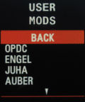
Language
Here you can set the menu language of the FIS-Control.Available languages: English, German, Danish, Czech, Dutch, Polish, French, Spanish, Italian and Lithuanian. Other languages can be added on request.
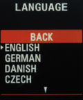

Collections
It is possible to define four collections for the preset view "collection". A collection is a set of up to six measurement values. These readings may be taken from different measurement groups of a control unit. You can also include the measurements of external sensors to a collection.First pick the collection you want to configure (1 to 4). Now you can setup each line (1 to 6). For every line you can select the measurement group that contains the specific value and which of the values you want.
This has to be repeated for all lines and all collections.
To select a collection go to SETTINGS -> PRESETS and choose the view COLLECTION for the preset. The FIS-Control will read the measurement group that is defined as GROUP directly after connecting to the defined control unit. So it is best to select a GROUP for the preset that is also used in the collection.
The meaning of the preset value is the number of the collection to use (1 to 4).
To include measurements from the external sensors to a collection, got to the collection configuration menu and set the GROUP to "0". The VALUE will specify, which external sensor to use. The assignment is as follows:
- Value 1 to 7 are the sensor inputs 1 to 7
- Value 8 is the on board ambient pressure sensor
- Value 9 and 10 are the both EGT inputs
- Value 11 to 16 are the GPS data (if a GPS mouse is connected to the FIS-Control)
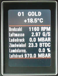
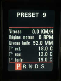
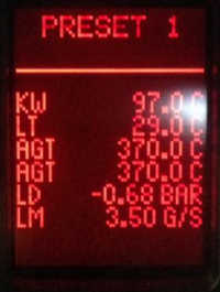
ECU Info
Here are three pages with informations about the current control unit.The first page shows the part number and the name of the control unit. Often the name includes the software version. Also the soft coding is shown.
The second page shows the address of the control unit and the actual baudrate that is used on the K line, or the nominal baudrate of the CAN bus.
Additionally you can see the workshop code. That is an identifier of the last workshop that changed the coding of the control unit. In the lower two lines, there is the amount of connection attempts that were needed to establish the current OBD connection and also which communication protocol is used (KWP1281, KWP2000, KWP2000 over CAN).
The third page shows additional text, if provided by the control unit.
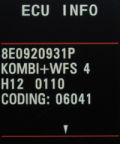
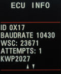
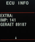
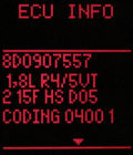
K-LINE<->UART
The FIS-Control can be used as OBD dongle.Via RS-232 it is compatible to VAG-COM (up to version 409.1), VCDS-lite, CarPort and WBH-Diag (up to version 0.89).
Via bluetooth it is compatible to WBH-Diag (version 1.0 an newer) and the Torque Pro Android app (not Torque Lite).
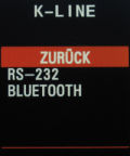
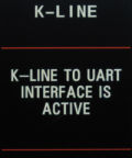
UART<->DIS
It is possible to send data to the cluster screen via the FIS-Control using RS-232 or bluetooth. Please contact me fore more information, if you want to use this feature.Snake
The FIS-Control offers many useful features... but there is also a useless one. Control a little snake in the cluster display using the buttons of the wiper stalk. Try to pick up as many fruits as possible without hitting the snakes tail or the walls.Info: Snake is not running in some Audi A4 (B6/B7).

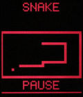
Relay drivers
The FIS-Control offers four relay outputs. This is helpful to switch lights or other stuff on and off.Every relay output can drive up to 600 mA.
Warning: A short circuit to ground of the relay output can permanently damage the FIS-Control.
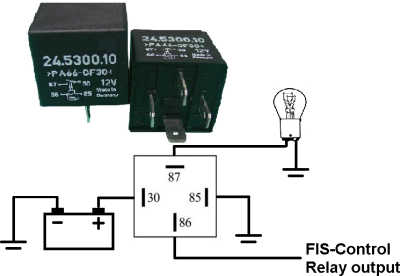
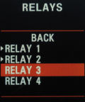
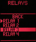
About
Here you can see, which firmware version is installed on the FIS-Control. On a second page there is a unique serial number for every FIS-Control.
Firmware updates
The FIS-Control can be updated to newer firmware that offers new features or has improvements and bugfixes.You may either use the RS-232 port or a wireless bluetooth connection to transfer the firmware file to the FIS-Control.
Info: The latest software is available on my website for free downloading.
The file always includes a complete firmware. There is no need to install prior updates. Just load the latest file to the unit.
Warning: Only use a battery powered laptop in the car.
The easiest way is to update the FIS-Control with the Android app.
- Turn off the ignition of your car
- Press and hold the Reset button on the bottom side of the wiper control stalk
- Turn on the ignition
- Wait about 5 seconds then release the button
- Repeat steps 1 to 4 again one time
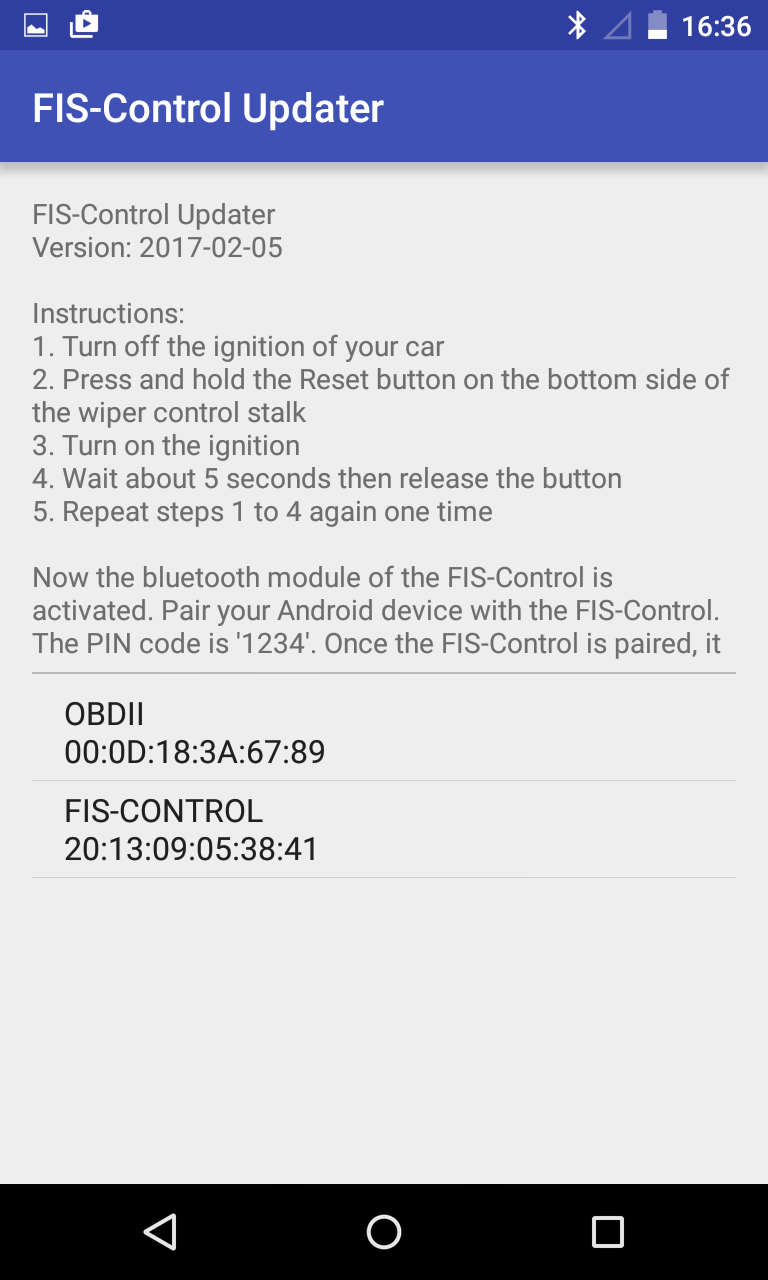
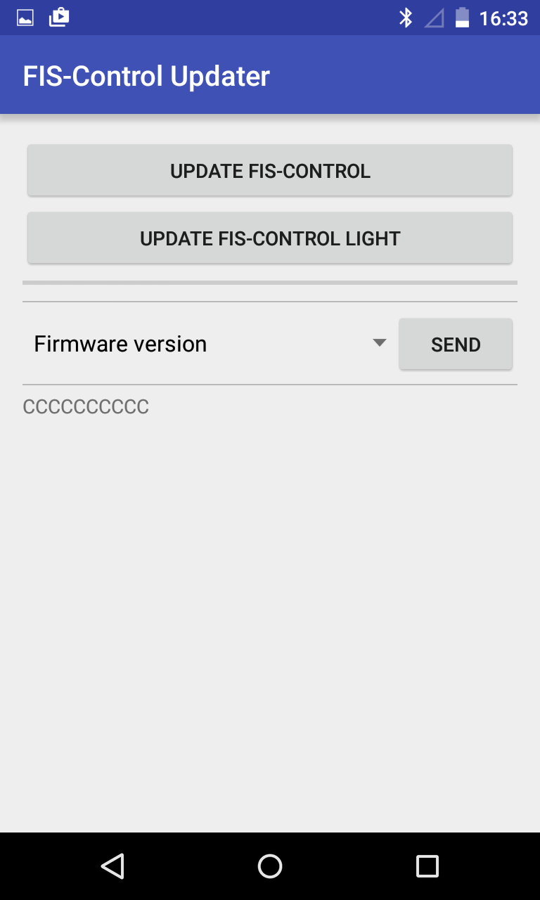
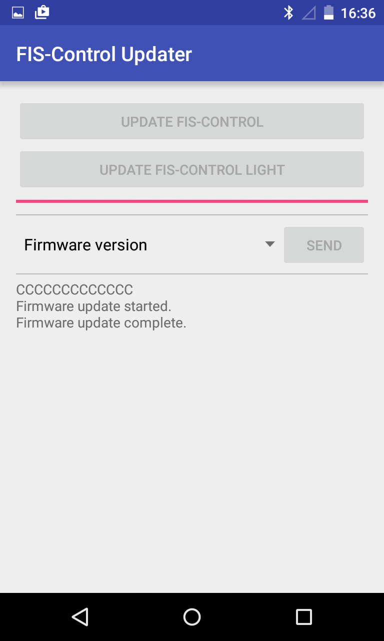
If the firmware shall be loaded via the serial port, you'll need a laptop with an RS232 interface or an USB-serial-adaptor.
Use a 9-pin straight cable. The so called null-modem cables don't work here,
- To update the firmware, the FIS-Control has to be started in software loading mode. This is done by press and holding the the Set button (not the Up or Down button) of the wiper stalk while the ignition is switched on.
Info: For the Audi A4 (B6/B7) wait about five seconds after turning on the ignition. Than switch off and on the ignition again without pressing any buttons of the wiper stalk. - (only needed for bluetooth)
Let the laptop search for bluetooth devices in range. The device "FIS-CONTROL" should be found. Pair the FIS-Control with the laptop. The PIN number is "1234".
The operating system should assign a COM-port to the new connection. - Start HyperTerminal (this tool comes with Windows XP: Start -> Programs -> Accessories -> Communications) or an other terminal tool, like TeraTerm or ZOC.
Choose the correct COM-port. If you are using the RS-232 port, use the following settings:- Bits per second: 115200
- Data bits: 8
- Parity: None
- Stop bits: 1
- Flow control: None
- Now the firmware can be transferred to the FIS-Control. Select "Transfer" -> "Send File" in the menu bar of HyperTerminal.
Now choose the firmware file and set the transfer protocol to "XModem". Now "Send".
The transfer should not take longer than 5 minutes. - Switch the ignition off and on again. In the "ABOUT" menu of the FIS-Control you can see the date of the currently loaded firmware version. This should match to the software you just loaded.
Troubleshooting
The FIS-Control does not start
If the FIS-Control does not appear after a long press to the Up key (at the side of the wiper stalk), this can have several reasons. If the FIS-Control has not worked before in the car, you should first check the cable connections.Next you can check if the FIS-Control is visible via Bluetooth after the ignition is turned on. You can use a laptop or an Android phone. An iPhone doesn't help.
If the FIS-Control is visible via Bluetooth, the good news is, that it is alive. The bad news is, that it has not entered its normal operating mode. In the normal operating mode, the Bluetooth module of the FIS-Control is disabled. An enabled Bluetooth module means, that the FIS-Control is either in software loading mode or in configuration mode.
If the FIS-Control could not establish a connection to the instrument cluster, it starts in configuration mode. Normally that means, that the FIS-Control or the instrument cluster are not properly coded. Both codings can easily be done with the FIS-Control Android app (download at www.fis-control.de).
Coding of the FIS-Control is explained here in the user manual: Coding of the FIS-Control
For most cars the setting "FIS-Control: Telematics/3LB" is correct. If the instrument cluster does not support the telematics channel (e.g. some Audi TT 8N and newer Audi A3 8P and TT 8J), you can use the setting "FIS-Control: Navigation" instead. This only works as long as there is no navigation system installed that already occupies that communication channel. If the FIS-Control shall share the navigation channel with the navigation system, you could set the mode "FIS-Control: Parallel". There are some restrictions in useability in this mode, though.
For cars of the Golf Mk5 platform, the mode "FIS-Control: DDP" is correct.
With the Android app, you can read the current coding with "firmware version".
Even without a phone or laptop, it is at least possible to switch between the two channels "Telematics/3LB" and "Navigation". Therefore you have to hold the Down button (at the side of the wiper stalk) and turn on the ignition. Now press the Up key one time and then restart the ignition.